What is a current transformer?
A current transformer is a type of instrument, used to measure or sense large alternating currents by scaling it to a smaller, safer and measurable value. It transforms the primary current to a proportional secondary value in terms of magnitude and phase. Current transformers are available in various sizes and shapes and are used as an interface between high currents and measuring/sensing devices. They are also known as CTs.
- What is a current transformer?
- Why are current transformers (CT) necessary?
- Working principle
- Caution: Never leave the secondary of a current transformer open-circuited!
- Types of current transformer based on construction
- High voltage current transformers
- Accuracy class and rated burden
- Current transformer ratings
- Current transformer error
- Error reduction in current transformer
- Uses of current transformers
Why are current transformers (CT) necessary?
It is difficult to make measurement devices such as an ammeter or a wattmeter(kWh) meter and protection relays that can carry hundreds or thousands of amperes. Also, higher voltage levels make these devices dangerous to connect. These barriers can be overcome using a CT. The turns ratio of a current transformer is made such that the full load current in it’s primary give a secondary current of either 5A or 1A.
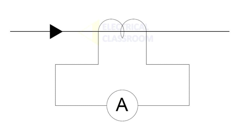
A current transformer is connected in series to the current-carrying conductor and an ammeter is connected to its secondary. The ammeter is arranged to give a full deflection with either 5A or 1A depending on the turns ratio of the CT. The ammeter’s scale is adjusted according to the turns ratio.
Working principle
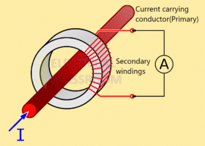
An alternating current is passed to the primary of the transformer and the measurement/sensing/protection device is connected to its secondary. The primary of a CT typically has only one turn, which is nothing but the current-carrying conductor passed through its window. It never has more than a very few numbers of turns in its primary. The secondary of the transformer has many turns depending on the magnitude of the current to be stepped down. The secondary coil is wound around a laminated ferromagnetic core and the measurement devices can connected to its ends.
The alternating current produces an alternating magnetic field in the ferromagnetic core. Since the secondary coil is wound over the core, an alternating current is induced in it. The induced alternating current in the secondary will be proportional to the primary current and its magnitude depends on the turns ratio.
The primary current and the full scale deflection current of the measurement devices determines the turns ratio of the a CT. In most case, the secondary current of a current transformer shall be 5A. Thus in the case of a hollow transformers designed to measure 1000A primary current, the turns ratio will be 1000/5, which means the secondary winding has 200 turns.
Caution: Never leave the secondary of a current transformer open-circuited!
If there is current flow in the primary of the current transformer and its secondary winding is kept closed, the current flowing through the secondary builds up a back EMF and counters the primary magnetizing force. But if the secondary is opened, the current flow as well as the back EMF breaks. Due to which an extremely high voltage appears at the secondary of the transformer which is dangerous to personnel and the CT itself. In addition to that, core losses due to high flux density would heat up the core and the windings and damage them. For this reason, the secondary of a current transformer should always be short-circuited before removing the device connected to its secondary.
Types of current transformer based on construction
Based on the type of construction, current transformers are classified into three types as follows:
- Window CT or toroidal CT
- Bar CT
- Wound CT
Window or toroidal current transformers
This type consists of a hollow core through which the current-carrying conductor or cable is passed. The conductor itself acts as a single turn primary winding. The core can be of solid or split type construction. Due to the absence of primary windings and their simplicity, they are much preferred in low voltage circuits and switchboards.
Bar-type current transformers
These contain a copper or aluminium busbar surrounded by the secondary winding wound over the ferromagnetic core. The busbar acts as a single turn primary winding. They are directly connected to the current-carrying conductor. They are also known as bar-primary CTs.
Wound current transformers
They have very similar construction to that of normal transformer. They have separate primary and secondary winding. The primary winding needs to be physically connected in series to current carrying conductor.
High voltage current transformers
CTs used in substations are usually mounted outdoors. They may contain multiple cores and secondary coils as well as added insulation. They are classified into four basic types: Hairpin tank type, Cascade/eye bolt type, Top core type and Combined current-voltage type.
Accuracy class and rated burden
Accuracy class describes how accurate the current transformation of a current transformer would be within when the burden within the allowable limits. Accuracy classes are defined by IEC and IEEE and are different for metering CTs and relaying CTs.
Accuracy classes for metering CTs: Metering devices such as ammeters, wattmeters, energy meters, kVar and kVarh meters requires high accuracy and has a low burden. The accuracy classed defined by IEC are 0.2 or 0,2S, 0.5 or 0.5S and those defined by IEEE are 0.15 or 0.15S, 0.3 or 0.6.
Accuracy class for relaying CTs: Relaying CTs requires lower accuracy. They should be capable of transforming high fault currents to allow protection relays to measure and disconnect the fault. The accuracy classed defined by IEC are 5P, 10P, PR, PX or TP and those defined by IEEE are C 100-800.
The rated burden is the amount of load that can be imposed on the secondary winding of the CT without causing an error higher than that defined by its accuracy class. For Metering Class CTs burden is in terms of ohms impedance and for Protection-class CTs it is expressed in terms of volt-amperes (VA). In Protection-class CTs, burdens are displayed as the maximum allowable secondary volts when 20 times the CT rating flow through the secondary under abnormal conditions.
Current transformer ratings
- Rated primary or secondary current: This the nominal current a CT primary and secondary are designed to handle.
- Rated transformation ratio: Thus is the ratio of primary and secondary rated current. This need not be equal to the primary and secondary turns ratio.
- Rated accuracy limit factor (RALF): The primary current up to which the CT is required to maintain its specified accuracy with rated secondary burden connected, expressed as a multiple of the rated primary current.
- Rated burden: An mentioned above, the burden is the amount of load that can be imposed on the secondary without causing an error higher than that defined by its accuracy class. Typical CT burdens as per IEC are 1.5 VA, 3 VA, 5 VA, 10 VA, 15 VA, 20 VA, 30 VA, 45 VA and 60 VA.
- Accuracy class: Accuracy class describes how accurate the current transformation of a current transformer would be within when the burden within the allowable limits.
- Phase displacement: It is the difference in the phasor difference between the primary and secondary currents.
- Knee point: The knee point of a CT is the point on the magnetizing curve at which an increase of 10% in the flux density causes an increase of 50% in the magnetizing current.
Current transformer error
Current Ratio Error expressed in percent is given by the formula:

Where:
Kn = Rated transformation ratio
Ip = Actual primary current
Is = Actual secondary current when Ip is flowing, under conditions of measurement
Error reduction in current transformer
Error in current transformer can be reduced by:
- By using Grain-oriented cold-rolled silicon steel.
- Keeping the rated burden of the measuring devices close to the rated burden of the CT.
- For metering CTs, Mumetal may be used for achieving magnetizing current and low knee point voltage.
Uses of current transformers
- Current transformers are used with ammeters, kWh meters, power factor meters and energy meters for current measurements.
- It is used to operate protective relays.
- It is used to activate the trip coil of a circuit breaker.
- Clamp meters are specially designed current measurement devices, that allows measurement of the current in a conductor by clamping it around a current carrying conductor.
Review:
Current transformers are used to step-down the primary current to a easy to measure secondary current. They isolate the measurement and sensing devices from the main circuit. A CT consists of one or a very few primary turns and can have several hundreds of secondary turns.
The primary of a CT is connected in series to the current-carrying conductor and measurement devices are connected to its secondary. The secondary of a CT cannot be left open-circuited because it may cause an abnormally high voltage to appear on the secondary and will damage the core and the windings.


Useful information on Current Transformers, Current Transformers are widely used in electrical industries,