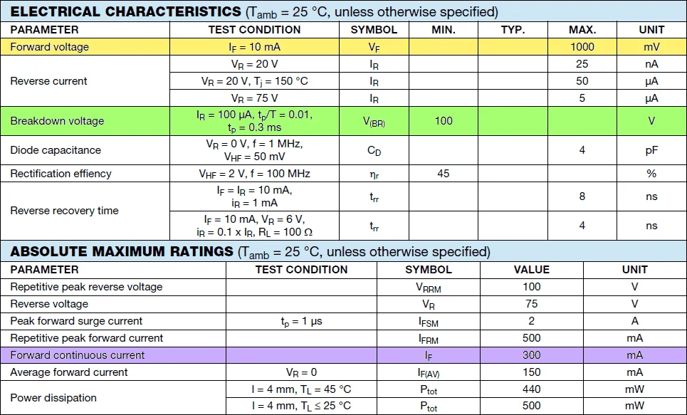
Datasheets released by diode manufacturers contain a number of diode ratings. In order to select diodes for an application, it is important to understand all the ratings listed in the datasheets. Here is a list of all diode ratings that you must remember always.
Diode ratings
- Diode ratings
- Forward voltage drop (Vf)
- Peak Inverse Voltage (PIV)
- Maximum repetitive reverse voltage (VRRM)
- Maximum DC reverse voltage, VR
- Forward voltage – VF
- Forward continuous current – IF
- Peak forward current – IFSM or Non-repetitive Peak Forward Surge Current
- Repetitive Peak Forward Surge Current – IFRM
- Maximum reverse current or leakage current – IR
- Maximum power dissipation – PDmax
- Maximum operating junction temperature – Tj
- Junction Capacitance – CD
- Reverse recovery time – Trr
- Reference:
Forward voltage drop (Vf)
The voltage drop measured across a forward-biased diode during conduction is known as forward voltage drop. A silicon diode has a forward voltage drop of 0.6V and a germanium diode has a forward voltage drop of 0.7V.
Peak Inverse Voltage (PIV)
Peak Inverse Voltage refers to the maximum reverse bias voltage a diode withstands without damaging itself, before breakdown. The peak inverse voltage is also known as peak reverse voltage. The peak inverse voltage rating of a diode increases and decreases with temperature. A typical diode used in rectifiers has a PIV rating of at least 50Vdc at room temperature.
Maximum repetitive reverse voltage (VRRM)
The maximum reverse voltage a diode can withstand in the form of repetitive pulses is known as Maximum repetitive reverse voltage (VRRM). In other words, it is the maximum reverse voltage that a diode can withstand when applied repeatedly. It is a very important diode rating, that is taken into account while selecting a diode for rectifiers.
Maximum DC reverse voltage, VR
Maximum DC reverse voltage, VR, is defined as the maximum continuous reverse-biased voltage a diode can withstand. The maximum DC reverse voltage is also known as the maximum DC blocking voltage (VDC).
Forward voltage – VF
A certain amount of voltage is required to trigger conduction in the forward direction. Forward voltage can be defined as the minimum voltage that when applied across diode triggers conduction in the diode. For silicon diodes, the typical forward voltage is around 0.7V and for germanium diode, the typical forward voltage is around 0.3V.

Forward continuous current – IF
The maximum forward continuous current is the maximum continuous current the diode can conduct safely without damaging itself. If the diode is forced to conduct more than the maximum forward current, the heat generated at the P-N junction can permanently damage the diode.
Peak forward current – IFSM or Non-repetitive Peak Forward Surge Current
The peak forward current is the maximum current surge that a diode can handle for a short period of time. It is one of the most important diode ratings that we must refer to. It is typically rated for 8.3 ms single Half-Sine-Wave of peak current. This is much higher than the rated maximum forward current. The continuous flow of forward surge current will instantly damage the diode.
Repetitive Peak Forward Surge Current – IFRM
The repetitive peak forward surge current is the maximum current surge the diode can handle as repetitive pulses without damaging itself.
Maximum reverse current or leakage current – IR
The maximum amount of current the diode can conduct during reverse bias is known as reverse leakage current or leakage current. It is negligible when compared to the forward continuous current. For an ideal diode, the leakage current assumed to be zero.
Maximum power dissipation – PDmax
Maximum power dissipation is the maximum possible power dissipation in the diode when operating in forward bias. It is typically the multiplication of forward voltage by the forward continuous current. The P-N junction offers a resistance to the current flow resulting in power loss in the form of heat across the junction.
Maximum operating junction temperature – Tj
The maximum operating junction temperature is the maximum allowable temperature at the P-N junction. This decides the life and proper operation of the diode. The maximum operating junction temperature is mention in degree Celsius and one of the important diode rating that need to be considered during selection.
Junction Capacitance – CD
The amount of capacitance measured between the anode and cathode of the diode under reverse bias is known as junction capacitance. When operating in reverse bias, the depletion region widens and acts like a dielectric medium that separates the anode and cathode of the diode. This results in junction capacitance. It is measured in pF.
Reverse recovery time – Trr
The amount of time a diode takes to stop conduction as the voltage across it alternates from forward-bias to reverse bias is known as the reverse recovery time. Theoretically, the diode must block the current flow instantaneously. The reverse recovery time of the diode is rated in nano-seconds.
Below is the list of all important diode ratings.

Out of all the diode ratings mentioned above, the highlighted ones are the most important.
Reference:
http://www.nhn.ou.edu/~bumm/ELAB/Lect_Notes/diodes_lecture_v1_2_2.html
