An earth leakage can represent a danger to life or property if it is not located and mitigated. Studies have revealed that at least 500 people experience electrocution every year in the US alone. Earth leakage relays can be helpful in sensing and mitigating such incidents.
What is earth leakage?
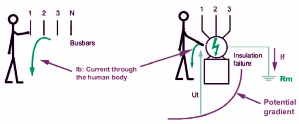
Earth leakage is an unindented situation in which a conductor carrying current comes in contact with the earth or chassis of equipment, either directly or indirectly, causing a current flow to the earth. Earth leakages can be a result of insulation failure or electric shock (current flows through the human body to the ground).

What is an earth leakage relay?
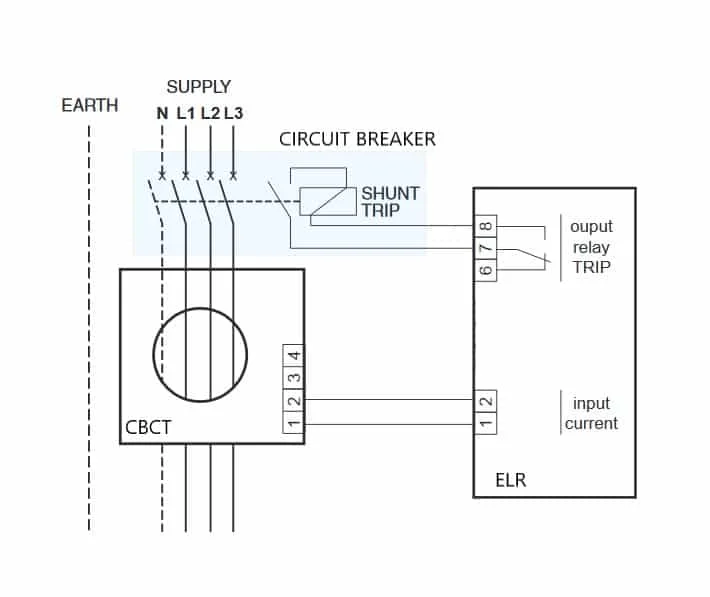
An earth leakage relay is a device used to sense earth leakages and open a circuit breaker when the leakage current exceeds the preset value. It can protect human beings from electrocution and prevent fire hazards. Earth leakage relays are used in combination with Core balance current transformers(CBCT) or Zero phase current transformer (ZCT).
Working principle
During an earth fault, the current flows directly to the earth by bypassing the load. This happens when a live conductor touches the earth directly or through the human body. This can be the result of insulation failures, wet surfaces or improper wiring.
Under normal conditions, the vector sum of the current flow in phase and neutral will be zero. Earth faults cause an imbalance in the current flow in the phase and neutral conductors (vector sum of the current would not be zero). Core balance current transformers or zero-phase current transformers are used to sense this current imbalance.

The earth fault relay continuously monitors the output of the CBCT. When its output exceeds the present limit (leakage current limits can be set) , the relay contacts operates. These relay contacts are used in the activate the trip contacts of the circuit breaker and trips it.
ELR Wiring diagram
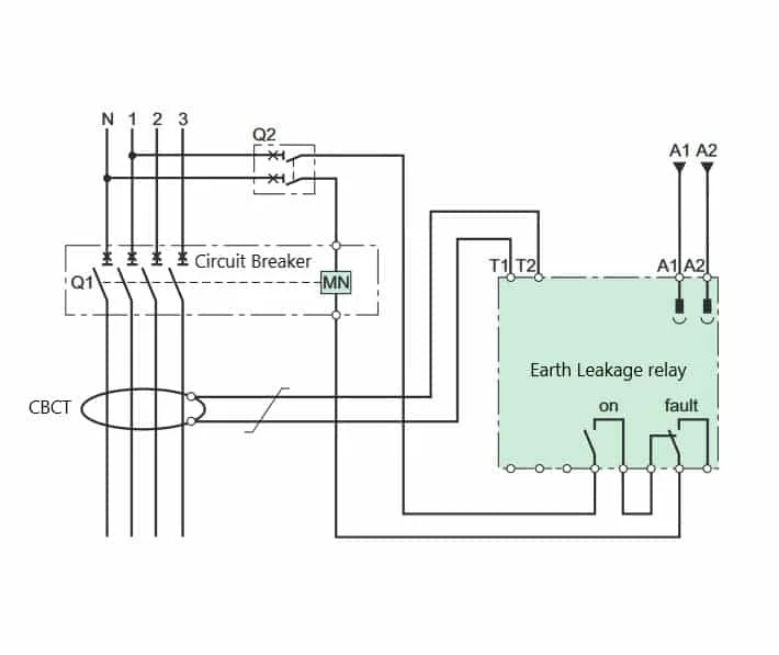
A typical wiring diagram of an earth leakage relay is shown below. Operational power is applied to the terminal A1 and A2 of the ELR and the CBCT is connected to the terminals T1 and T2. The normally closed terminals of the fault signalling contacts are connected to the Undervoltage release coil of the circuit breaker. So when the leakage current sensed by the CBCT exceeds the set value, the ELR interrupts the power to the Undervoltage release and breaker trips immediately.

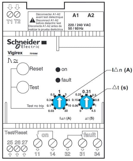
Earth leakage relays can detect leakage before potential damage is caused. The leakage current limit needs to be adjusted between 10mA and 3A based on the application. IEC/EN 60755 defines general rules for residual-current protection devices.

Good Morning
Kindly quote the following
1.RELAY EARTH LEAKAGE CORE BALANCE CURRENT: 500mA VOLTAGE: 550V PN: Ms2-A1-500
Regards
Mwaka Nachilombe
How the elr function in 3 phase supply without neutral if leakage happened?
For 3 phase three-wire system, the vector sum of currents in all three phases is zero. Any imbalance will induce a current in the CBCT. If the current exceeds the preset value, the ELR trips.
it is working phase unbalancing detected and operated relay earth fault.
How ug series cbct trip mccb when when neuttraland all phases (4 cables) passing inside cbct ? and how to solve this issues ?
Kindly refer the drawing shown above. https://www.electricalclassroom.com/earth-leakage-relay-elr/#3-elr-wiring-diagram- .The contacts of the earth leakage relay is connected to the shunt trip coil of the MCCB.
Thanks for the Imformation team. Please send me the drawings of different types of electrical connection of earth leakage relays
I want power panel board wiring diagram
How does Zero pottential transfomer pick up when a person is elctricuted to protect him/her.
When netrual pass through CT where does it go to the field?
Because if only 3 lines passes through CT it will only measure imbalance so I want to know that when neutral passes through CT where does it go to the field.
All the four lines must pass through the CBCT.
This is a useful article to refresh my knowledge on this key electrical component. Thanks for sharing.