Electricity does not exist naturally in any useful form. It has to be generated from any other sources of energy such as solar, wind, hydro, thermal, atom, etc. Photovoltaic cells help us trap energy from the sunlight and generators are used to convert mechanical power available in other forms to electricity. The mechanical power can be obtained from wind, flowing water, and steam using turbines. Motors are used to convert back the electricity to mechanical power. So, collectively, electric machines are devices that convert mechanical energy to electrical energy and vice versa.
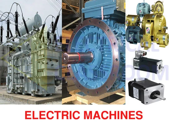
Let’s start with transformers so that you can understand the basic concept of electromagnetic induction that happens in every electric machine.
Classification of Electric machines
Basically electric machines are classified into
- Static Electric machines – Transformers
- Rotating Electric machines – Motors (convert electrical energy to mechanical energy) and Generators (convert mechanical energy to electrical energy)
Transformers
Any static device that can transfer alternating current from one circuit to another circuit by electro-magnetic induction can be considered as a transformer. Transformers are used to transform alternating current from one voltage level to another voltage level.
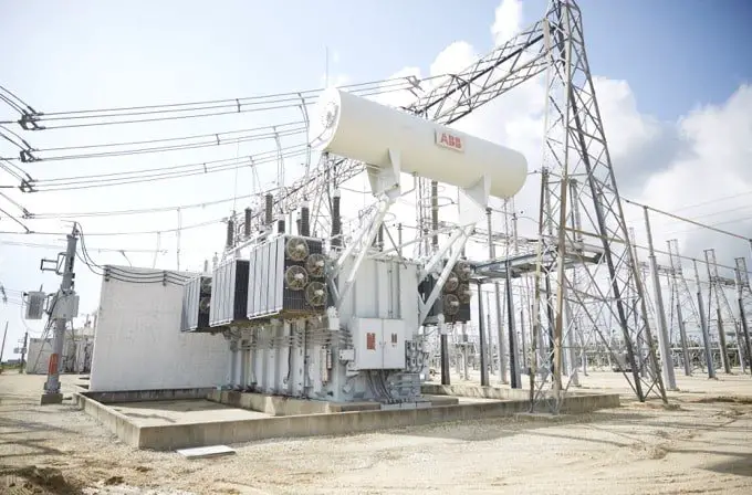
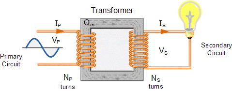
A basic transformer consists of two coils that are coupled using a magnetic core. In the case of three-phase transformers, two sets of coil per phase will be present. One set of coils is known as the primary winding and the other is known as the secondary winding. These two windings are insulated from each other and are magnetically coupled through the iron core.
The alternating voltage is connected to the primary winding. When connected, an alternating magnetic flux is produced at amplitude proportional to the magnitude of the applied voltage, frequency and the number of turns. This flux links with the secondary winding and induces a voltage proportional to the number of secondary turns.
The ratio of the number of primary turns and the secondary turns is known as the turns ratio of the transformer. Any ratio of voltage transformation is possible and can be achieved by properly proportioning the number of primary and secondary turns.
The voltage transformation ratio is given by:
If the secondary voltage is greater than the primary voltage, the transformer is called step-up transformer. If the primary voltage is greater than the secondary voltage then the transformer is called step down transformer.
In order to ensure effective linking of magnetic flux, the core (the structure that supports the windings) is made up of highly permeable iron or steel alloy. Transformers are available in various sizes, forms and structures but the basic principle remains the same.
Electric power is generated at the generating station at medium voltages (6.6kV, 11kV, 33kV). In order to minimize transmission losses, the generated voltage is raised to higher voltages. This is where step-up transformers are used. Step down transformers is used to lower the transmitted voltage near the load centers. This makes the transformer the most important electric machine.
Rotating electric machines
The rotating electric machines used to either convert mechanical energy to electrical energy or vice versa. There are three basic types of rotating electric machines.
- DC electric machines – DC motors and DC generators
- Synchronous machines – Alternators and Synchronous motors
- Induction motors or Asynchronous machines
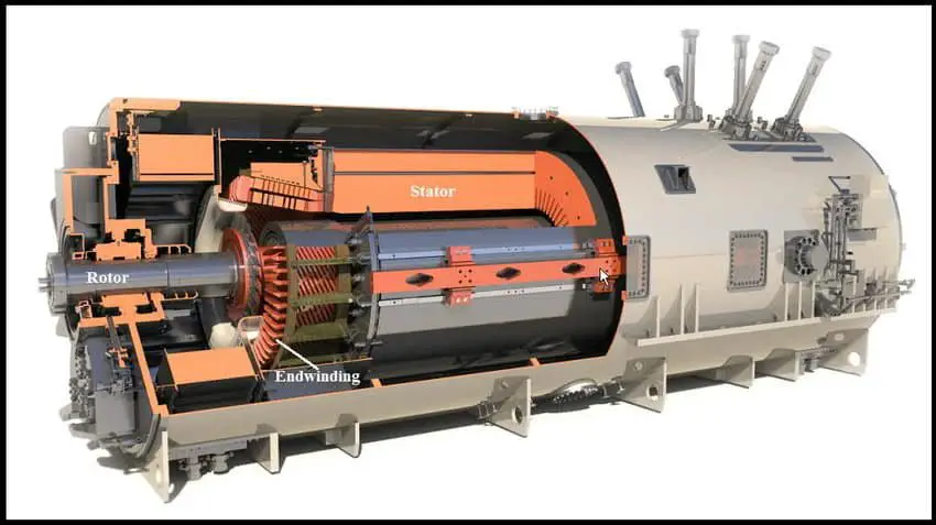
All rotating electric machines have two basic parts in common. The first is the rotating part known as the rotor and the second is the stationary part called the stator. These parts are made up of highly permeable magnetic material such as silicon steel. Let us dive into the details of each one of them.
DC Machines
DC machines are available in different sizes and forms from small stepper motors in printers to huge traction motors. A DC machine consists of field winding at the stator and armature at the rotor.
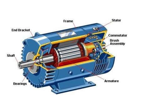
As you know an electromagnetic conversion requires relative motion between the field and armature windings. To achieve relative motion between the stator and the rotor, the armature is rotated externally using a prime mover (turbines or engines). When the armature is rotated past the excited field poles, EMF is induced in the armature.
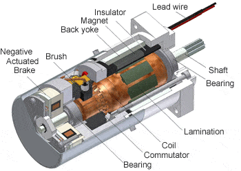
The induced EMF is alternating in nature. In order to convert it to DC, the two ends of the armature are connected to commutator. Commutators are metallic bars fitted to the shaft of the machines and connected to armature winding, which shift the direction of current each half turn. A commutator is divided into multiple segments and each segment is insulated from each other. Carbon brushes are used to collect the current from the commutator.
In DC machines armature always stays at the rotor in order to convert the induced alternating voltage to direct voltage. The armature consists of several slots and is mounted on the shaft which is supported on the bearing.
DC motors and DC generators have a same design. Generally a motor can be used as a generator and vice versa. Based on the stator and rotor winding connections, a DC machine can be classified as follows:
- Separately excited DC machine
- Self excited DC machine
Separately excited DC machines
In this type, the armature and field windings are excited separately. Field winding can be replaced by a permanent magnet also.
Self Excited Motors
The armature and field windings of the self excited motor are excited from the same power supply. The following connections are possible.
- Shunt connection – The armature and the field are connected in parallel.
- Series connection – The armature and the field are connected in series.
- Compound connection

DC motors
The constructional features of a DC motors are same as that of generators. They work on the property of attraction between unlike magnetic poles and repulsion between like magnetic poles. By adjusting the field and armature voltages the speed of a DC motor can be controlled. Also, different types of excitation methods make DC motors more versatile.
Speed torque characteristics of DC motors

Synchronous machines
Alternators present in almost all turbine-driven power generation stations across the world are synchronous machines. An alternator can also function as a motor if the DC supply is applied to the rotor and AC voltage is applied to the stator. We will see in brief the principle of operation of synchronous machines.
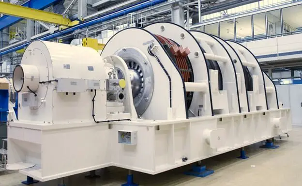
A synchronous machine has its armature at its stator and field at its rotor. DC power is applied to the rotor (field winding) which turns it into an electromagnet. In a PMDC (permanent magnet DC) machine, the rotor field winding is replaced with a permanent magnet.
The rotor can be either cylindrical type or salient pole type. The cylindrical; rotors are mechanically stable at high speeds and are used in large turbo generators, whereas the salient pole machines are used in low-speed hydroelectric generators.
Principle of operation of synchronous machines
Alternators
When DC voltage is applied to the rotor, it becomes an electromagnet. If the rotor is driven by a prime mover, a relative motion happens between the rotor magnetic flux and the stator conductor. Therefore according to faraday’s law, an EMF is induced in the stator winding. The induced EMF is alternating in nature and the frequency of alternation will be proportional to the speed of rotation of the rotor.
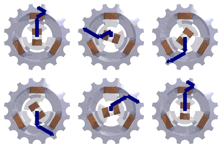
In a three-phase alternator, three sets of coils wound at the stator poles at a relative electrical spacing of 120 degrees. Therefore the EMF induced in each set of coil shall have a phase shift of 120 degrees.
Synchronous motors
As mentioned earlier, DC voltage is applied to the field winding of the synchronous motor and an AC supply is applied to the stator in order to generate torque. The torque is generated due to the tendency of the rotor to align itself to the magnetic field produced by the stator.
When a three-phase AC voltage is applied to the stator, a rotating magnetic field is produced. Since the rotor is already has a constant magnetic field, it tries to align itself to the rotating magnetic field of the stator field, thus generating a torque.
The rotor cannot pick up speed instantly due to inertia. Also, the speed of rotation of the stator field is very fast (50Hz or 60Hz). Hence it becomes difficult for the rotor to pick up torque initially. This makes the synchronous motor non-self starting one. The motor should be driven by another auxiliary means close to its synchronous speed. At close to synchronous speed the rotor and stator fields get locked to each other and the rotor starts rotating at the synchronous speed, after which the auxiliary means used to start the motor can be de-coupled.
Another feature of a synchronous motor is that when it is overexcited, it acts as a capacitor and can be used for reactive power compensation. The motor used for reactive power compensation is known as a synchronous condenser and is used in large power installations for power factor correction.
Induction motors or Asynchronous motors
Induction motors are widely used in all industries. Without any doubt, one can say that it is the most used electrical machine in the world. Single-phase induction motor can be found at every home in the form of ceiling fans, pumps, etc. the biggest advantage of induction motors is that it does not require a separate power supply for the rotor.
Principle of operation of induction motors
The induction motors have three-phase winding at the stator similar to that in synchronous machines. When a three-phase voltage is applied to the stator coils, a rotating magnetic field is formed. This varying magnetic field comes in contact with the rotor conductors and induces EMF in it.
The ends of rotor winding are short circuited so that there flows a current proportional to the induced EMF. Due to the current flow, another magnetic field rotating in the direction same as that of the stator is setup. The interaction between these two magnetic fields generates a torque that tends to rotate the motor in the direction of rotating magnetic field of the stator. Induction motors are self starting motors.
The speed of the rotor is always less than the synchronous speed of the applied stator voltage. Hence these motors are known as asynchronous motors. The per unit difference between the synchronous speed and the actual rotor speed is known as slip.
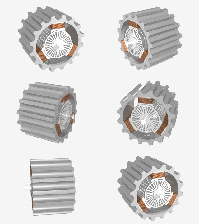
Two types of rotor constructions are possible in induction motors. The first is wound rotor and the other is squirrel cage rotor. The rotor consists of slots to accommodate conductors. The wound rotor consists of three phase windings similar to that of stator in these slots. One end of each phase is shorted to form a WYE or star connection and the other ends brought to the slip ring attached to the shaft.
Carbon brushes are used to tap the slip rings to the external terminal box. External resistance can be added to the rotor to limit the starting current.
The squirrel cage rotors consist of solid bars of conducting material placed in the rotor slots. These conductors are shorted at the both ends. This type of rotors does not have any external electrical connections. Also motors with squirrel cage rotor have lesser starting torque than the wound rotors.
Induction Generators
When an induction motor spinning at certain speed is forced to spin above its synchronous speed by applying an external mechanical power, it acts as a generator. Such machines are known as asynchronous generators. They find their application in wind power generation and small hydro power plants.
Permanent Magnet DC motors
Permanent Magnet DC motors consist of radially placed permanent magnets at the stator. The rotor consists of DC winding connected to the commutator. The principle of operation of a PMDC motors is same as that of a DC shunt motor except that they do not require separate field supply. Absence of field supply decreases power loss, improves efficiency and reduces size when compared to conventional DC motors of same size.
Brushless DC Motor
A brushless DC motor has a set of permanent magnets at the rotor and semiconductor switched at the stator. Semiconductor switches convert the input DC supply to pulsating DC to generate maximum torque at a given speed.
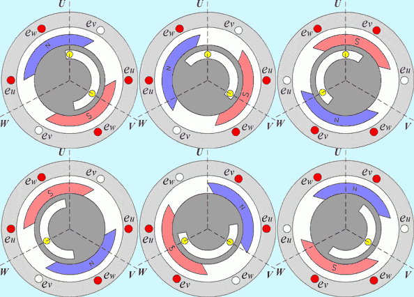
In these motors, the position of the rotor and the stator are inverted. The field is present in the rotor and the armature is present at the start. Sensors are used to position the rotor and based on its position the semiconductor switches are turned ON and OFF to fulfill the speed-torque requirements. These motors are more expensive than the conventional DC motors, require lesser maintenance and have longer operating life than conventional DC motors.
Servomotor
Servomotors are used for precise position control. They are brushless DC motors combined with position sensing devices such as encoders and potentiometers. Servo motors are used for closed-loop position control. They find their application in marine navigation, automatic machine tools, air crafts, robots, speed governors etc.
Stepper motors
Stepped motors are pulse driven motors used for position control. These motors can move through a specific angle for each control phase applied. They do not require position sensors.
How do I reference this page?