In order to understand the equivalent circuit of a transformer, we suggest you read Ideal transformer first and then come back and continue from this point.
What is an equivalent circuit of a transformer?
Equivalent circuit of a transformer is a schematic representation of a practical transformer that shows all electrical parameters such as winding resistance, reactance, admittance, susceptance, primary and secondary voltages, currents etc. Now let’s dive into the topic and first of all, let’s get introduced to an actual transformer.
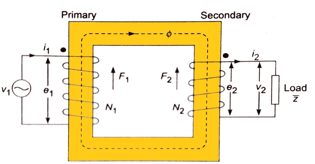
The figure shows a representation of a real transformer with load connected to its secondary. As you know the primary and secondary conductors have a finite amount of resistance.
Let R1 be the resistance of the primary coil and R2 be the resistance of the secondary coil. When current flow through these coils, a certain amount of power is lost due to its ohmic resistance. As the conductor is made of copper, the power loss is otherwise known as the copper loss.
Consider that the transformer has N1 number of primary turns and N2 number of secondary turns. V1 be the voltage applied to the primary coil which induces an emf E1 in the primary coil and E2 in the secondary coil.
A load impedance Z is added to the secondary terminals such that it drains a current I2 from the transformer secondary which is proportional to I1 at the transformer primary. Let V2 be the voltage measured across the load.
The major part pf the flux Φ links the primary and secondary winding and is confined within the core while a small amount of which leaks to the surrounding air. Let ΦPL and ΦSL be the leakage flux linking the primary and secondary coils respectively.
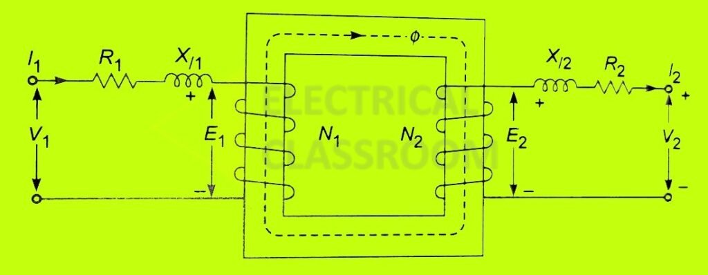
The primary and secondary coils both possess resistance (R1 and R2) and reactance (Xl1 and Xl2) and have a series effect on the winding.
In addition to all the above, there exists a magnetizing current and a core loss component of current which are denoted by Im and Ii respectively. As you know, the power transformation ratio of the transformer is given by
The voltage drop due to the resistance and the leakage reactance are too small so that
Equivalent circuit of a transformer
Hope you understood all the assumptions and considerations made. Now its time to draw the equivalent circuit of a transformer.
As said earlier, transformers draw an exciting current Io, having a magnetizing component Im, that generates a flux Φ and a core loss component Ii. With all the above details lets construct a circuit model for a real transformer.
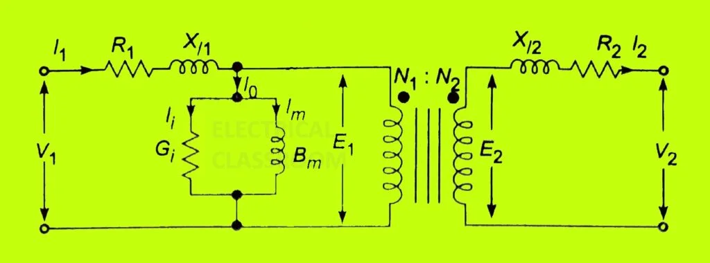
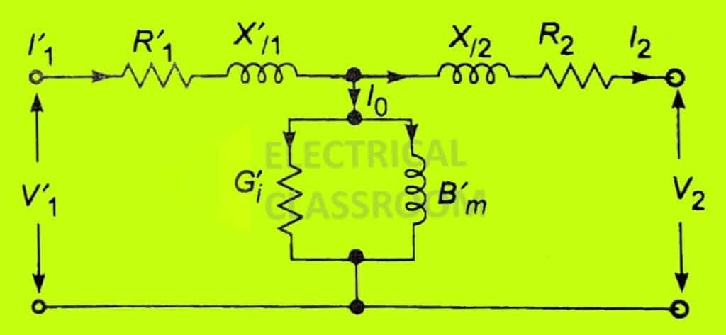
Where Gi and Bm represents the core loss and the magnetization component respectively.
As discussed in Ideal transformer, the secondary resistance and reactance can be referred from the primary side as follows:
Similarly,

Figure (b) shows the resultant circuit.
After referring the impedances, voltage and current to primary side the representation of core is no more necessary. Therefore, the circuit can be reduced to a T-circuit as in figure (C).
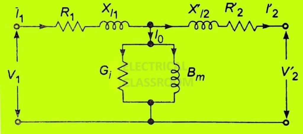
Similarly, the equivalent circuit can be referred to the secondary by transforming the impedance and admittance of primary to the secondary by multiplying it by the square of the turns ratio.
Phasor diagram of a transformer
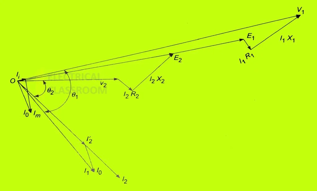
With reference to the equivalent circuit of the transformer, the phasor diagram of a transformer can be drawn.
Applying Kirchoff’s voltage law on figure
