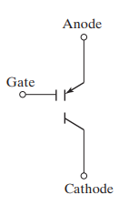
An MCT or a MOS-controlled Thyristor is a semiconductor device with the combined capabilities of a thyristor and a MOSFET. It was introduced in the year 1992. It comes with several advantages when compared to other semiconductor devices. Its vertical structure allows low conduction loss and high voltage capabilities.
The silicon-controlled rectifiers have a very high current density and low forward conduction losses but cannot turn off by applying gate pulse. On the other hand, MOSFETs have a high input impedance, ease of control, and higher switching speeds, but a lower current density and higher forward drop.
An effort to combine the advantages of an SCR and MOSFET has resulted in MCTs. They can be turned ON by applying a negative voltage to their gate and turned off by applying a positive pulse. In addition, it is a high power, high frequency, low conduction drop, and a rugged device.
Structure of a MOS Controlled Thyristor
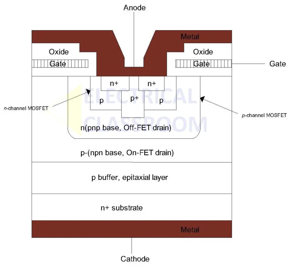
The basic structure of an MCT is shown in the figure below. It has a punch-through structure and combines the features of a regenerative thyristor and a MOS-gate structure. The structure is such that the MOSFETs are arranged on top of an SCR. The structure can be understood better with the help of the equivalent diagram.
The equivalent diagram consists of an n-channel MOSFET (M2) and a p-channel MOSFET (M1). Two transistors—NPN (Q1) and PNP (Q2) —represent the NPNP structure of MCT. The two transistors in the equivalent circuit indicate that the MCT, like any other thyristor, has regenerative feedback.
Of the two MOSFETs, the n-channel MOSFET (M1), connected across the emitter and collector of the transistor (Q2), helps to turn on the MCT, and the p-channel MOSFET (M2), connected across the emitter and base of the transistor (Q1), helps to turn it off.
Turn ON
While in the forward blocking state, applying a negative pulse to a p-channel MCT’s gate with respect to the anode will cause it to turn ON. An n-channel MCT can be turned on by applying a positive pulse to its gate with respect to the cathode. Until the device current is reversed or a turn-off pulse is applied to the gate, an MCT is in the ON-state.
When a negative pulse to a p-channel MCT, the MOSFET (M1) passes the gate current through the base of Q1 and switches it ON. The current from the anode flow through M1 to the base of Q1 and then its emitter and collector. As the collector of Q1 is connected to the base of Q2, the collector current of Q1 will turn ON Q2. This pushes the MOS Controlled Transistor to the conduction mode.
Turn OFF
A p-channel MCT in the on-state can be turned off by applying a positive pulse to its gate with respect to the anode. And an n-channel in the on-state can be turned off by applying a positive pulse to its gate with respect to the cathode.
When off-pulse is applied to the MOSFET (M2), the Q2 transistor is short-circuited across its emitter and base terminals. The anode current now flows through the MOSFET (M2) and the current reaching the Q1 transistor decreases. When the MOSFET (M2) is switched on, the minority carriers for the upper base region are removed. This results in injecting fewer amount of carriers from the upper emitter region. This poses a hindrance to the regeneration process, therefore breaking the latching condition. As a result of these conditions, the MCT is turned off which would break the latching condition. It is integral that MOSFET (M1) is now kept off when switching MOSFET (M2).
If the MCT’s current is less than the peak controllable current, it can be used as a gate-controlled device. Attempting to turn them off at currents greater than the rated peak controllable current may damage the device. For higher current values, the MCT must be commutated off like a standard SCR. For smaller device currents, gate pulse widths are unimportant. The width of the turn-off pulse should be increased for higher currents. Also, the gate draws a peak current during turn-off.
Characteristics of MCT
- It can be turned on or off by a negative or positive gate voltage.
- It has high-speed switching capabilities.
- Since it has a higher gate input impedance than a GTO and hence requires less gate turn-off current, its gating requirements are simpler.
- Low conduction losses.
- It has a higher current density when compared to MOSFET.
Applications
- Discharge Applications, Smart Munitions
- Commonly used in circuit breakers
- Electric Vehicles
- SmartVars
- Induction heating
- MCT is used in power applications that require high power conversion.
- They are also used as forced committed power switches.
References:


