Every motor must be protected from all possible faults to ensure prolonged and safe operation as well as time loss caused due to breakdown. Almost all industries rely on the electric motor to control their processes and production. Hence it is necessary to make the motor fail-safe.
The most vulnerable part of a motor is its winding insulation. The winding insulations are at high risk of damage by excessively high temperatures. Overload relay is one such device that protects a motor from damage caused due to overloads and over-currents. It is used with contactors and can be found in motor control centers and motor starters.
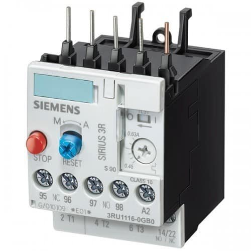
Definition of overload relay
An overload relay is a device that protects an electric motor against overloads and phase failure.
It senses the overloading of the motor and interrupts the power flow to the motor, thus protecting it from overheating and winding damages. Apart from overloads, it can also protect the motor from phase loss/ failures and phase imbalance. They are very commonly known as OLR.
What is an overload?
An overload is a condition at which a motor draws a current above its rated value, for a prolonged period.
It is the most encountered fault and can result in temperature rise in the motor winding. Hence the rapid return to normal operation is important.
Principle of operation
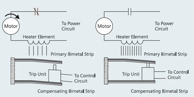
A thermal overload relay works in the principle of electro-thermal properties in a bimetallic strip. It is placed in the motor circuit in such a way that the current to the motor flows through its poles. The bimetallic strip gets heated up by the current directly or indirectly and when the current flow exceeds the set value, it bends.
They always work in combination with contactors. When the bimetallic strips heat up, the trip contact is activated that in turn breaks the power supply to the contactor coil, de-energizing it and breaking the current flow to the motor. This tripping time is always inversely proportional to the current flow through the OLR. Hence higher the current flow faster shall it trips. Therefore, thermal overload relays are referred to as current-dependent and inversely time-delayed relays.
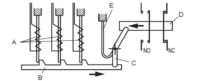
B = Trip slide
C = Trip lever
D = Contact lever
E = Compensation bimetal strip
Credit: Rockwell
Types of overload relays
Overload relays can be classified as follows:
- Bimetallic thermal overload relays
- Electronic overload relays
The working principle of the above differs a little from each other. Let us discuss it in the following sections.
Working of bimetallic thermal overload relay
As explained above, a bimetallic thermal relay works on the heating property of the bimetallic strip. In the direct heating method, the full current to the motor flows through the OLR. Therefore, it gets heated up directly by the current.
But in the case of indirect heating, the bimetallic strip is held in close contact with the current-carrying conductor inside the OLR. Excessive current flow to the motor heats up the conductor and hence the bimetallic strip. The conductor shall be insulated hence no current flow through the strip.
Working of electronic overload relay
Electronic overload relays do not have a bimetallic strip inside. Instead, it uses temperature sensors or current transformers to sense the amount of current flowing to the motor. It uses microprocessor-based technology for protection. Temperature is sensed using PTC and the same is used to trip the circuit in case of overload faults. Some electronic overload relays come with current transformers and Hall effect sensors that directly sense the amount of current flow.
The major advantage of electronic OLR over thermal OLR is that lack of bimetallic strip results in low heat losses inside the relay. Also, Electronic relays are more precise than thermal relays. Some manufacturers build electronic relays with extensive features such as earth fault protection, motor stall protection, etc. Electronic overload relays are much suited for applications that require a frequent start and stop of motors.
In addition, manufacturers offer built-in RTD or thermocouples that can be directly used to measure the winding temperature. These measurements can be used for more accurate thermal overload protection.
They are designed in such a way to withstand the starting current (which is typically 6 to 10 times the full load current) of the motor for a limited period (typically 15-30 seconds depending on the threshold of current).
Parts of a thermal overload relay
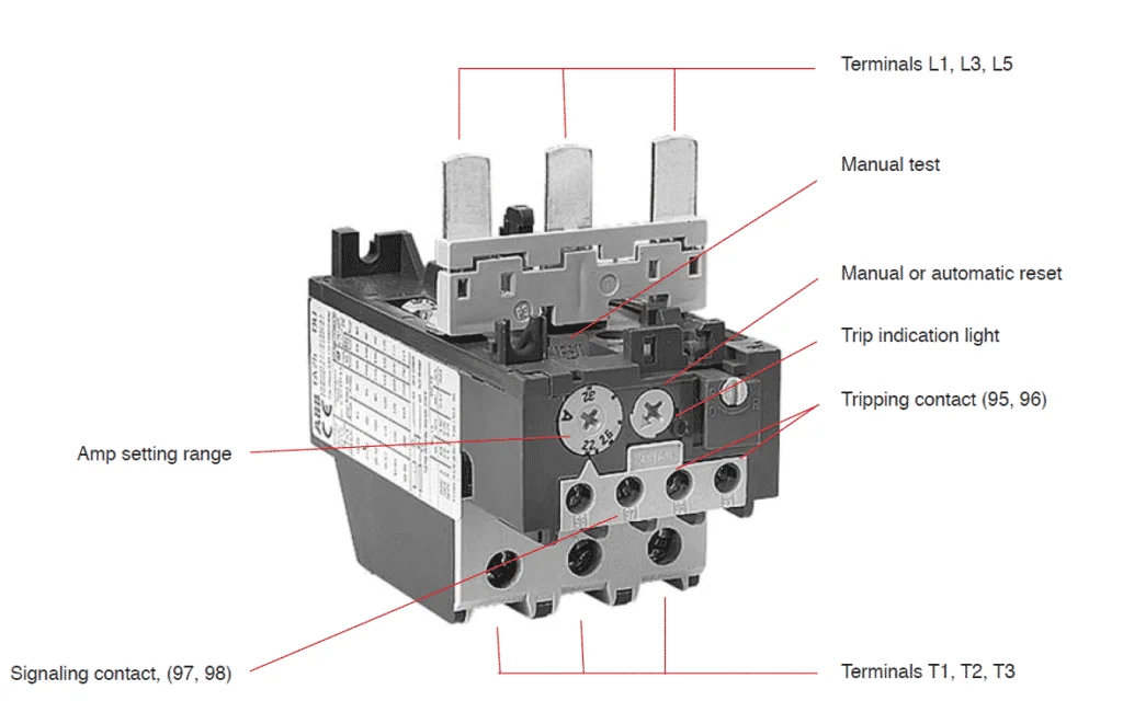
Apart from the bimetallic strip and contacts discussed in the working principle section above, there are a few more parts in an overload relay that needs to be understood.
Terminal
Terminals L1, L2, and L3 are input terminals. It can be directly mounted to the contactor. Supply to the motor can be connected to Terminals T1, T2, and T3.
Ampere range setting
A rotary knob is present over the overload relay. Using this knob, the rated current of the motor can be set. The current can be set between the upper and lower limits provided. In the case of an electronic overload relay, an additional knob for tripping class selection is also provided.
Reset Button
A reset button is present over the overload relay to reset the overload relay after a trip and clearance of fault.
Manual/Auto reset selection
With the manual/auto reset selection button, we can choose between manual and automatic reset of these relays after a trip. If the device is set to auto, a remote reset of OLR is possible.
Auxiliary contact
They are provided with two auxiliary contacts – one NO (97-98) and another NC (95-96). NO contact is for trip signaling and NC contact is for disconnecting the contactor. NC contacts should be capable of direct switching of contactor coil.
Test button
Using the test button, it is possible to test the control wiring.
Symbol of an overload relay
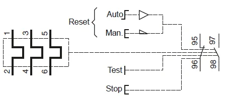
Here 1, 2, 3, 4, 5 and 6 are power terminal 95 & 96 are trip contacts and 97 & 98 are signaling contacts. Learn how to use them in a circuit here: Star-Delta starter wiring diagram – Control and power wiring diagrams
Frequently asked questions
What is the trip Class of overload relay?
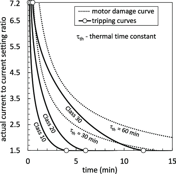
The time taken by them to open the contactor during overloads is specified by the trip class. It is commonly classified into Class 10, Class 20, Class 30, and Class 5. The OLR trips in 10 seconds, 20 seconds, 30 seconds, and 5 seconds respectively at 600% of full load current to the motor.
Class 10 and Class 20 are very commonly used ones. Class 30 overload relays are used for the protection of motors driving high inertia loads and Class 5 relays are used for the motors requiring very fast tripping.

How to use an overload relay in a circuit?
They are always used in combination with the contactors in the circuit. It is connected in line with the motor such that the current to the motor fully flow through it. Below are the various types of connections for single-phase and three-phase motors.
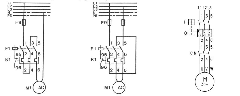
Read more: Sizing of contactor and overload relay for 3 Phase DOL starter
Read more on star delta starters: Star-delta starter (Wye-Delta Starters) – Circuit, working.
Read more about contactors: Contactor – Construction, Operation, Application and Selection
What causes the OLR trip?
As discussed above, there are three major conditions for overload trips:
- Overloading of the motor.
- Input phase loss
- Phase imbalance.
Apart from these, there may be some additional protection features available. This varies from one manufacturer to the other.
How does an overload relay protect from phase failures?
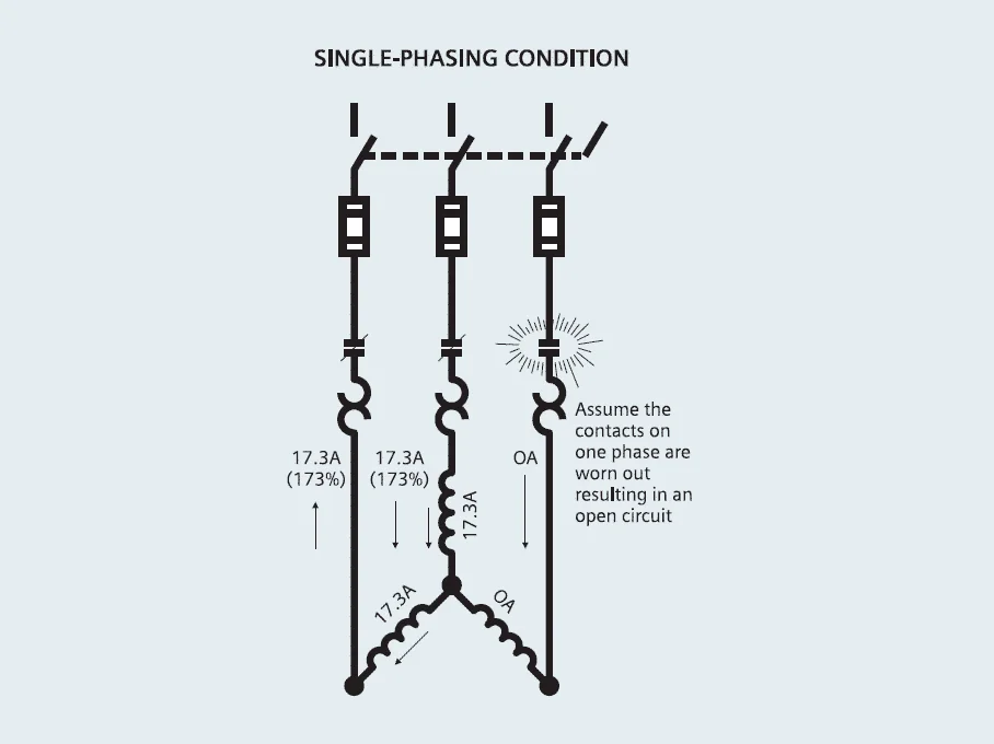
During normal operation, the current flowing through each pole of an overload relay to the motor remains the same at a time. If anyone of the phase is interrupted, the current through the other two phases rises to 1.73 times the normal value. Hence the overload relay gets heated up and it trips. Phase failure is also known as single phasing of motor or phase loss.
Can OLR protect from short circuits?
Overload relays cannot protect against short circuits. They should always be used with short circuit protection devices. Otherwise, any short circuits in the motor can potentially damage them. They can protect against overloads, phase loss, and phase imbalance, but not short circuits.
What could damage an overload relay?
The device will be damaged if the backup short circuit protection device (circuit breaker or fuse) is overrated. This may also damage the whole starter and even the motor windings themselves. Therefore it is advised to stick on to the maximum short circuit protection advised by the relay manufacturer.
Summary
An overload relay is a device that can protect a motor from overloads, phase failure, and phase imbalances. Based on the principle of operation they are classified into thermal and electronic overload relays. Thermal OLR is based on the principle of deformation of a bimetallic strip on heating. The electronic overload relay is a microprocessor-based device and comes with extensive built-in functionalities.
OLRs are used in combination with the contactors. It opens the contactor whenever it senses a fault. The time taken by them in opening the contactor during overloads is specified by their trip class. Overload relays cannot protect against short circuits. This sample datasheet can help you understand the relay ratings. They could be easily damaged if underrated or under with an overrated short circuit protection device (Fuse or Circuit breaker).
Nice work👍
Excellently described. Brief, to the point and comprehensive text.
thanks a lot, very ” to the points of importance”