The transformer facilitates the delivery of power electric energy at minimum power loss. The basic parts of a transformer are the core, the primary winding, and the secondary winding. Apart from these parts, there are various other components such as insulation, transformer oil, cooling arrangements, protection relays, enclosure, etc present in larger transformers. Let’s discuss the working principle of a transformer first and then see the parts of a transformer in this article.
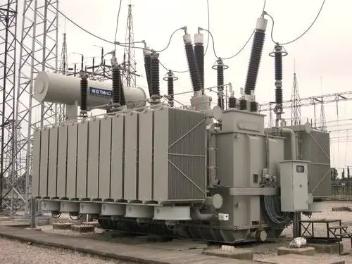
Transformer – Principle of operation
A transformer is a static device that works on the principle of electromagnetic induction. When an alternating current flows in the primary winding of a transformer, a varying electromagnetic field is generated which induces EMF in the secondary winding. The magnitude of the induced EMF is proportional to the turns ratio.
Parts of a transformer
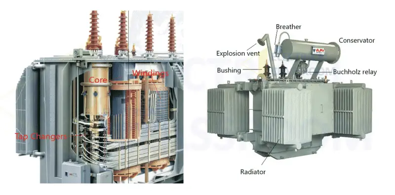
The following are the various transformer parts:
- Core
- Winding
- Insulation
- Tank
- Terminals and bushings
- Transformer oil
- Oil Conservator
- Breather
- Radiators and fans
- Explosion vent
- Tap Changers
- Buchholz relay
1. Core
The core provides a low reluctance path for electromagnetic flux and supports the primary and secondary windings. It is made by stacking thin sheets of high-grade grain-oriented steel which are separated by thin insulating material. To minimize the hysteresis and eddy currents, the carbon content of the core steel is maintained below 0.1%. When it is alloyed with silicon, eddy currents can be reduced.
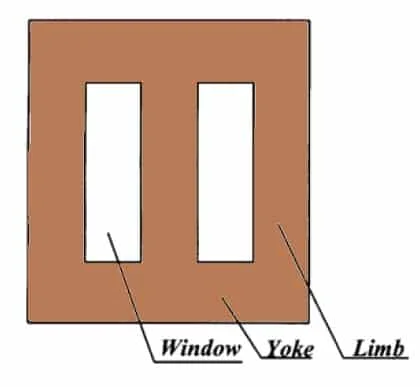
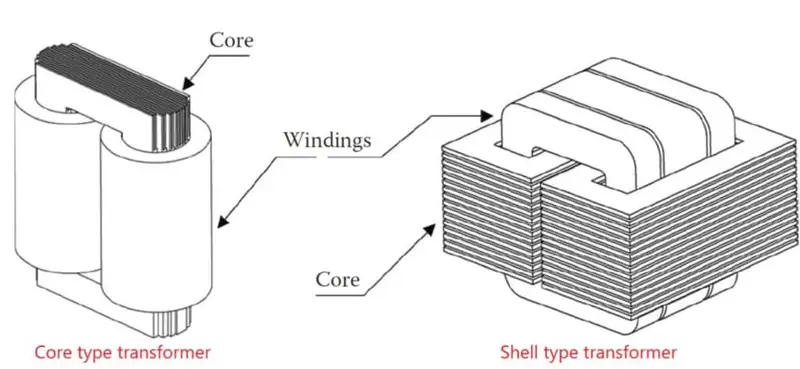
A typical three-phase transformer core is shown in the picture above. Each limb carries the primary and secondary winding of each phase. The limbs are magnetically coupled by the yokes. There are two types of core constructions: core type and shell type. In shell-type construction, the windings are surrounded by the core as shown below:
To know more about transformer cores, their construction, and design principles refer: Transformer core
2. Winding
The transformer carries two sets of winding per phase – Primary winding and secondary winding. These winding consists of several turns of copper or aluminum conductors, insulated from each other and the transformer core. The type and arrangement of winding used for transformers depend upon the current rating, short circuit strength, temperature rise, impedance, and surge voltages.
Out of the primary winding and secondary winding, the one that is rated for higher voltage is known as High voltage (HV) winding and the other is known as Low voltage (LV) winding.
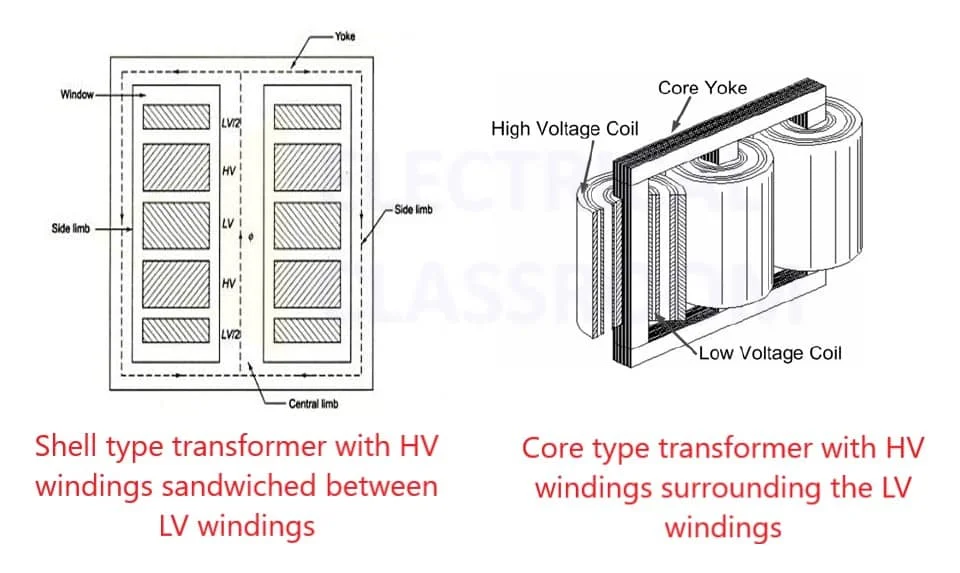
The high-voltage winding conductors are thinner than the low-voltage conductors and surround the LV winding from the outside. The LV winding is placed close to the core.
In shell-type transformers, the winding is split into several coils (few turns of a conductor). The HV coils are sandwiched between the LV coils. Whereas in core-type transformers, windings are classified into four types: Multi-layer windings, Helical windings, Disc winding, and foil winding. The choice of winding type is determined by the number of turns and its current carrying capacity.
Read more about various types of transformer windings: Types of Transformer windings
3. Insulation
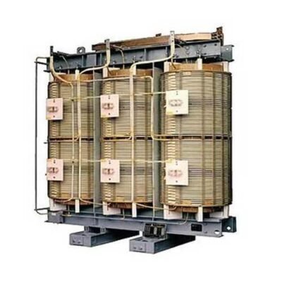
Insulation is the most important part of transformers. Insulation failures can cause the most severe damage to transformers. Insulation is required between the windings and the core, between windings, between each turn of the winding, and between all current-carrying parts and the tank. The insulators should have high dielectric strength, good mechanical properties, and high-temperature withstandability. Synthetic materials, paper, cotton, etc are used as insulation in transformers.
The core, winding, and insulation are the most basic parts of a transformer and are present in all types.
Learn more about insulators: Insulation materials used in transformers
4. Tank
The main tank is a part of a transformer that serves two purposes:
- Protects the core and the windings from the external environment.
- Serves as a container for oil and support for all other transformer accessories.
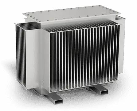
Tank bodies are made by fabricating rolled steel plates into containers. They are provided with lifting hooks and cooling tubes. To reduce weight and stray losses, aluminum sheets are also used instead of steel plates. However, aluminum tanks are costlier than steel ones.
5. Terminal and bushings
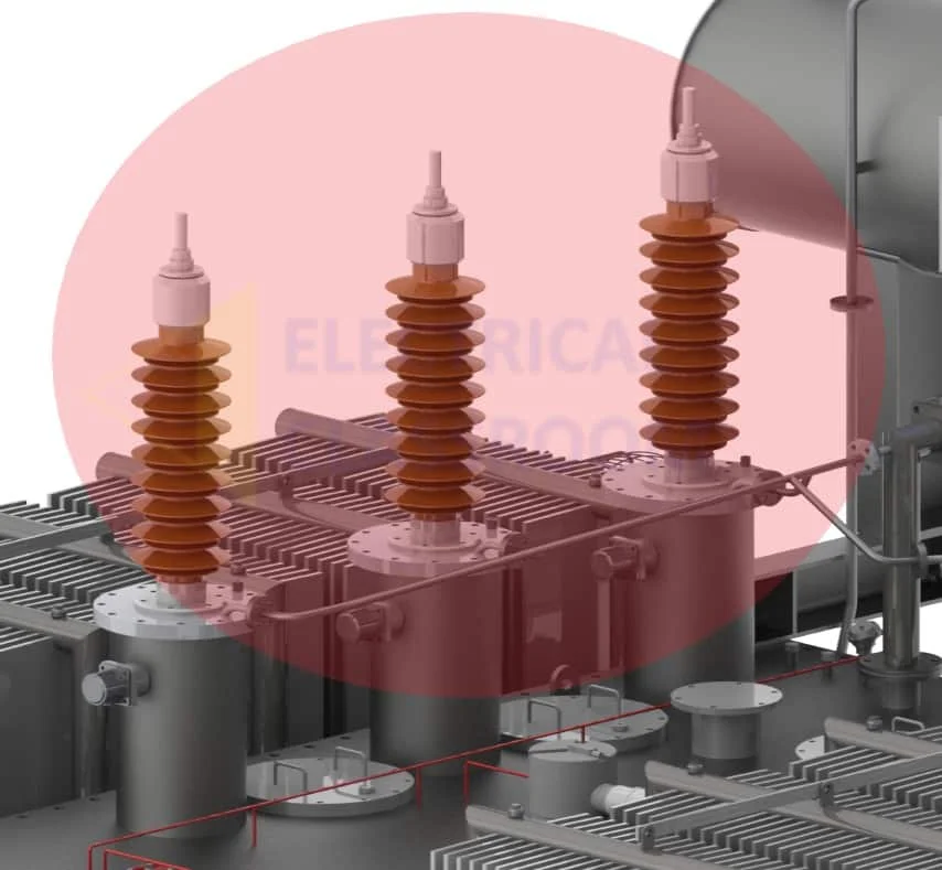
For connecting incoming and outgoing cables, terminals are present in transformers. They are mounted upon the bushings and connected to the windings’ ends.
Bushings are insulators that form a barrier between the terminals and the tank. They are mounted over the transformer tanks. They are a safe passage for the conductors connecting terminals to the windings. They are made from porcelain or epoxy resins.
6. Transformer oil
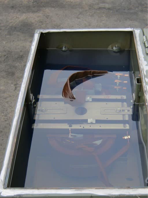
In all oil-immersed transformers, transformer oil provides added insulation between the conducting parts, better heat dissipation, and fault detection features. Hydro-carbon mineral oil is used as transformer oil. It is composed of aromatics, paraffin, naphthenes, and olefins. Transformer oil has a flashpoint of 310 degrees Celsius, a relative permeability of 2.7, and a density of 0.96 kg/cm3.
7. Oil Conservators
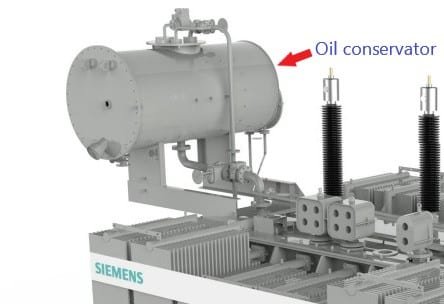
The oil conservator is moved on top of the transformers and is located well above the tank and bushings. Normally a rubber bladder is present in some oil conservators. The transformer oil expands and contracts with an increase and decrease in temperature. The oil conservator provides adequate space for oil expansion. It is connected to the main tank through a pipe. A level indicator is fitted to the conservator to indicate the oil level inside.
8. Breather
Breather is present in all oil-immersed transformers that have a conservator tank. It is necessary to keep the oil free from moisture. As the temperature variations cause the transformer oil to expand and contract, air flows in and out of the conservator tank. This air should be free from moisture. Breather serves this purpose.
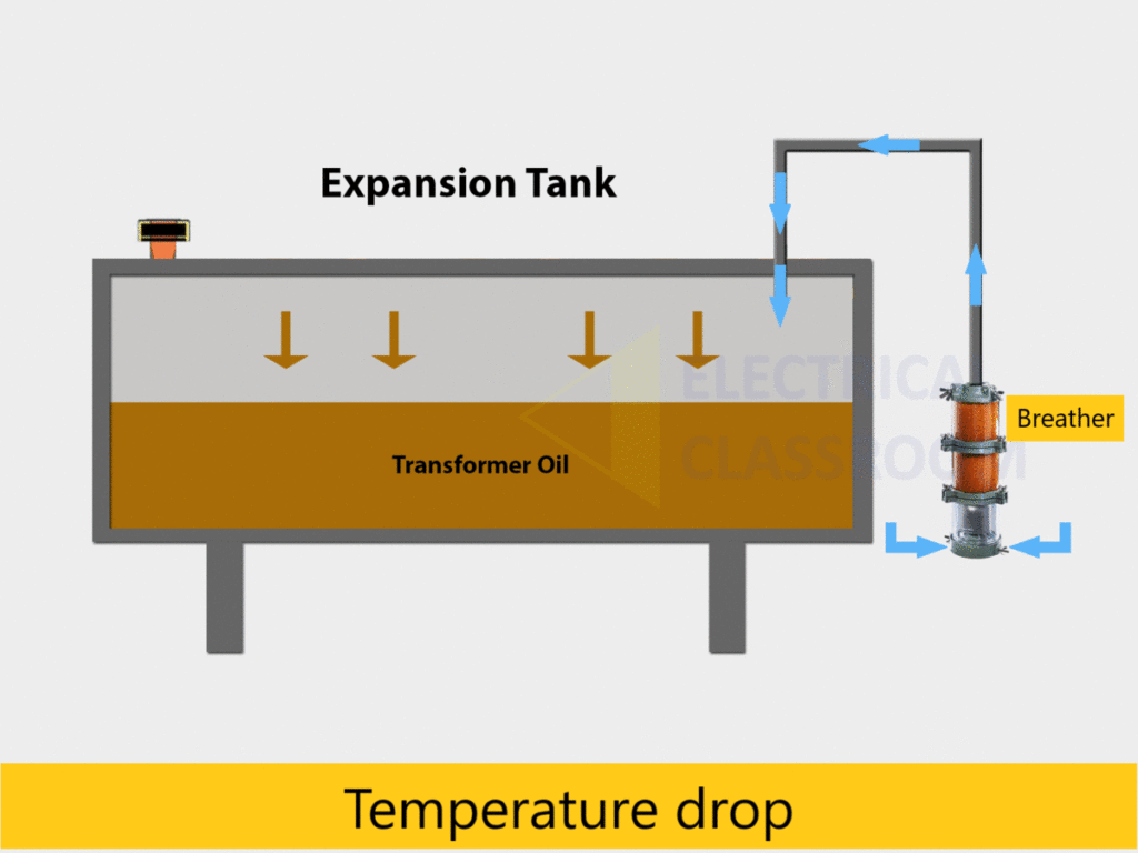
A breather is attached to the end of the air pipe such that the air enters and exits the conservator through it. The silica gel present in the breathers removes moisture from the air and delivers moisture-free air to the conservator.
9. Radiators and fans
The power lost in the transformer is dissipated in the form of heat. Dry transformers are mostly natural air-cooled. But when it comes to oil-immersed transformers, a variety of cooling methods are followed. Depending on the kVA rating, power losses, and level of cooling requirements, radiators and cooling fans are mounted on the transformer tank.

The heat generated in the core and winding is passed to the surrounding transformer oil. This heat is dissipated at the radiator. In larger transformers forced cooling is achieved with the help of cooling fans fitted to the radiators.
Read More: Transformer cooling methods
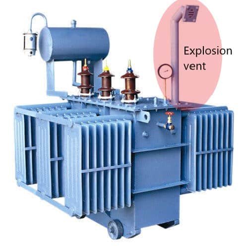
10. Explosion vent
An explosion vent acts as an emergency exit for oil and air gases inside a transformer. It is a metallic pipe with a diaphragm at one end, held slightly above the conservator tank. Faults occurring under oil elevate the pressure inside the tank to dangerous levels. Under such circumstances, the diaphragm ruptures at a relatively low pressure to release the forces from within the transformer to the atmosphere.
11. Tap changers
Tap changers are used to adjust the secondary voltage of transformers. They are designed to change the turn ratio of the transformer as required. There are two types of tap changers: On-load tap changers and Off-load tap changers.
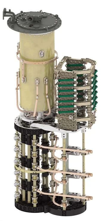
Off-load tap changers are designed to operate only when the transformer is not supplying any loads whereas on-load tap changers are capable of operating without interrupting the current flow to the load. Automatic tap changers are also available.
12. Buchholz relay
Buchholz relay is one of the most important parts of a transformer rated over 500kVA (Oil immersed transformer). It is an oil and gas actuated relay that is used to sense faults occurring in the parts immersed in the oil.
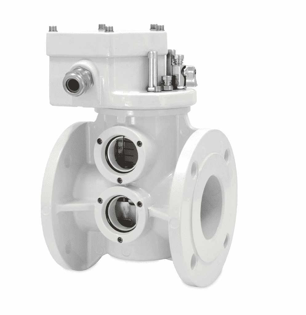
Short circuits occurring under the transformer oil generate enough heat to decompose the oil into hydrogen, carbon monoxide, methane, etc. These gases gradually move toward the conservator tank through the connecting pipe. Buchholz relay, which is mounted on the pipe connecting the conservator tank and the main tank, senses these gases and activates the trip and alarm circuits. The trip circuit opens the circuit breaker supplying current to the primary winding and interrupts the current flow.
Read more about the Buchholz relays, their construction, and their operation in detail here.
Apart from all the parts of a transformer discussed above, there are many other sensing instruments (temperature sensors, pressure sensors, etc.), indicators, protection relays, heat exchangers (for efficient cooling), and valves present in huge transformers. They are application-specific and are present in huge transformers.
Awesome post…excellent
To read in Hindi about transformer visit.
I is very useful to electricians
very vital for electricians to understand
Fully Satisfied , Great explanation
Very good explanation about transformers…thanks
VERY NINCE
Very educative
Thanks very much,,,,I have learned a lot
Thanks to you a lot, very usefull
nice expression
very nice and ,good knowledge of transformer
good explanation about transformer and very help full for electrician.
it was very useful information thanks
Very educative
It’s very awesome for good explanation
Very helpful post and thanks for sharing.
Thank you for your professional and understandable explanation.
As an electrician, it was the perfect explanation for the transformers for biggenners. Thanks for your efforts.