Potential transformers (PT) or voltage transformers are instrument transformers used for voltage measurements. They are connected in parallel to the line and operates under the same principle of power transformers. They cannot be used used to supply raw power to the loads. They have an accurate voltage ratio and phase relationship between primary and secondary windings. To understand the principle of operation of electric transformers better, kindly read: Transformer – Operation, construction and types.
Definition of potential transformers or voltage transformer
A potential transformer (PT) is a static device used to step down high voltages to measurable levels in order to facilitate measurement and controllability. Low voltages are easy to measure and can be used to operate protection relays.
The electric power is transmitted and distributed at various high voltages. These voltages need to be stepped down to the rated voltage of measurement devices for voltage measurements. Also, measurement devices cannot be directly connected to high voltage circuits for measurement. In addition to that, it improves the compatibility of standard measuring devices.
The principle of operation of potential transformers
The principle of operation of a potential transformer is the same as a normal transformer. It works on the principle of mutual inductance and Faraday’s law of electromagnetic induction. The flow of alternating current through a conductor produces a varying magnetic field. When another conductor is brought in contact with this magnetic field, voltage is induced in it. According to Faraday’s law, the magnitude of the induced voltage depends on the rate of change of magnetic flux linking the second coil and the number of turns.
ε =-N dΦ/dt
In the case of transformers, Since the rate of change of magnetic flux between the coils is almost the same, the induced voltage depends on the number of turns of the coils.
Construction of a PT
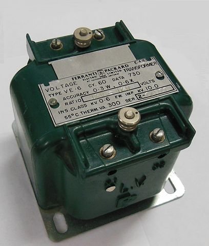
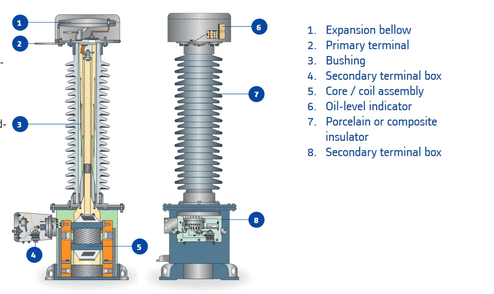
The above image shows the construction of a voltage transformer. It can be noted that the construction of a voltage transformer is slightly different from that of a power transformer. It has a core or shell type magnetic circuit(core). The coils are wound over one leg of the core. The primary and secondary windings are insulated from each other. In some medium and high voltage transformers, tertiary windings are also present. The primary winding consists of a large number of turns, whereas the secondary winding consists of only a fewer number of turns.
Types of potential transformers
There are three types of potential transformer: Electromagnetic induction type, capacitive-coupled type and optical type. The construction features of the electromagnetic induction type potential transformers are discussed above.
Capacitive-coupled Voltage Transformer (CCVT)
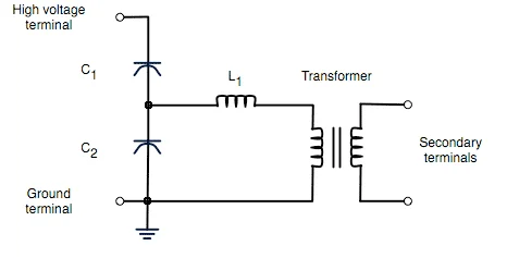
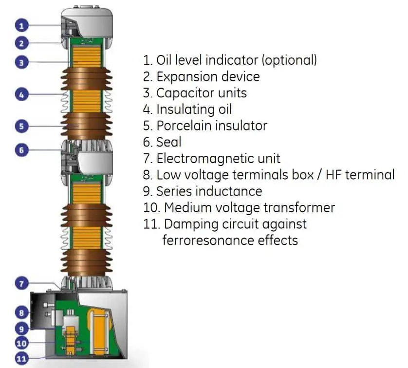
A capacitive-coupled voltage transformer is a combination of capacitance voltage divider and electromagnetic type PT. It is a cost effective alternative to electromagnetic PT. It has three parts: A capacitance potential divider, a tuning reactor and an isolation transformer as shown in the below figure.
The capacitor potential divider circuit consists of two capacitors C1 and C2 connected across the high voltage line and the ground. C1 is a series connection of several small capacitors. The majority of voltage is dropped across C1. The tuning reactor is used to tune the circuit for the line frequency. In addition to that, a tuning reactor enhances the energy transfer. The isolation transformer isolates the measuring instrument from the resonant circuit.
Optical Voltage Transformer
An optical voltage transformer works on the principle of Kerr effect, by which the light which is reflected from a magnetized surface may change both polarization and reflected intensity. This reflected light is measured optically and converted to an analog signal proportional to the applied voltage. This analog signal can be measured by using suitable instrument. Since there is no magnetic core and windings, these transformers are significantly smaller the CCVT and conventional PT. Optical voltage transformers are rarely used because of their complexity and high initial cost.
Potential transformer connection
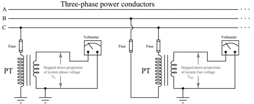
Potential transformers come with either two-bushings or a single bushing. Single bushing types are strictly for line to ground connections and two-bushing types can either be connected line-to-line or line-to-ground. Polarity of the winding must be taken in consideration during the connection. The measurement devices can be connected to the secondary of the voltage transformer. A typical connection diagram of voltage transformer is shown below:
Technical Specification
Burden
The external impedance in the secondary circuit in ohms at the specified power factor. It is usually mentioned in VA. It is the maximum amount of load that can be connected to the secondary of the VT without causing a higher error.
Accuracy class
Accuracy class defines how accurate the voltage transformer can be when the burden is below its rated value. The accuracy class, according to IEC, is given as 0.2, 0.5 or 1.0 depending on the application when a rated burden of around 1.3-1.5 times the connected burden will give maximum accuracy.
very well written post. Everything explained clearly.