In an AC power system, the power factor is a very important parameter that defines how efficiently electrical power is being utilized by the load. It is a rational number between -1 and 1 but has no unit. The p.f of a system depends on the type of load present, whether resistive, inductive, or capacitive. The inductive and capacitive load has a negative impact on the p.f. of the system. Poor p.f results in an increase in current drained by the load.
Definition of power factor
Power factor can be defined as the ratio of real power (Active power) to apparent power. It can also be defined as the absolute value of the cosine of the phase shift between the voltage and current in an AC circuit. It is denoted by the Greek alphabet λ (Lambda).
Power factor (λ) = Active power/Apparent power
= VI.COS φ/ VI
= COS φ
‘V’ is voltages in Volts
‘I’ is current in Amperes
‘Φ’ is the phase angle between voltage and current
Active power (kW)
It is the true power transmitted to the load for energy conversion. For example, a motor consumes the true power from the circuit and converts it into mechanical power, whereas lamps, on the other hand, convert the same into light. It is represented by the letter P.
Reactive power (kW)
Reactive power is the power required to produce the magnetic field in motors and transformers and has a direct impact on the p.f. It is represented by the letter Q.
Apparent power (kVA)
Apparent power is the product of voltage and current consumed by a load irrespective of its phase angle. It is the combination of real and reactive powers. It is represented by the letter S.
Read More: Real, Reactive, Complex and Apparent power
Unity power factor
Unity power factor is considered as a perfect scenario, during which apparent power and the real power shall be in phase. When the load is purely resistive, the current flow to the load will be linear and hence the phase shift between the voltage and current will be zero and cos Φ will be unity.
If the power factor cos φ=1 it means that there is no reactive power flow and the phase angle between the voltage and current is zero.
Leading power factor
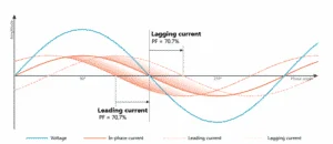
The P.F is considered to be leading if the apparent power leads the real power (true power), (i.e.) the current leads voltage. Capacitive loads cause the current to lead the voltage so as the power factor.
Lagging power factor
The P.F. is considered to be leading if the apparent power lags the real power (true power), (i.e.) the current lags voltage. Inductive loads cause the current to lag the voltage so as the p.f.
Power factor Calculation
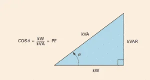
From the power triangle:
Power factor = Real power/Apparent power
Also,
Also,
Why is power factor improvement important?
Power factor improvement aims at optimal utilization of electrical power, reduction of electricity bills, and reduction of power loss.
- Power transformers are independent of P.F. If the power factor is close to unity, for the same KVA rating of the transformer more load can be connected. (Better the power factor lesser will be the current flow).
- Penalties imposed by the power utility companies for non-maintenance of optimal p.f. can be avoided.
- Optimal sizing of power cables is possible if the power factor. Low p.f. results in higher copper loss (I2R) loss also more voltage shall be dropped across the cable.
Power factor correction techniques
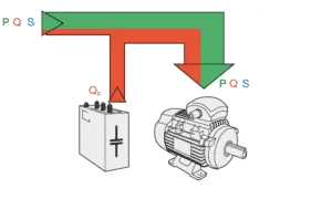
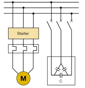
Most of the power loads are inductive and cause the current to lag the voltage. In order to overcome this few power factor correction techniques are adapted, which helps in neutralizing this lagging current. The most common P.F. correction technique is the usage of static capacitors in parallel to the load. Static capacitors supply leading current to the system and reduce the lag. Capacitor banks are connected in parallel to inductive loads. These capacitors are switched using a contactor based on the requirement. Static VAR compensators are also used for p.f. correction. These are power electronic versions of reactive power compensators and make use of thyristors for capacitor switching instead of contactors.
Other power factor correction techniques include connecting synchronous compensators parallel to the load. They are synchronous motors that run at no load. When a synchronous motor is overexcited and runs at no-load it acts as a capacitor and supplies reactive power to the network. Synchronous compensators are connected in parallel to the load.
Power factor correction calculation
Appropriate power factor corrective measure has to be taken for maintaining the required power factor of the system. Most of the time, engineers opt for capacitor banks for p.f. correction. Here is how the capacitor is required for p.f. correction is determined:
We can measure the supply voltage using a voltmeter and the current drawn by the load using an ammeter. From these data we can calculate the current p.f., apparent power, and reactive power consumed by the load, using the formulae below.
Apparent power = V x I (Measured using ammeter and voltmeter)
Current power factor = Load KW (Real power) / Apparent power
From the power triangle:
Reactive power (kVAR) = Sq.rt((Apparent power-kVA)2 – (Real power-kW)2)
And,
From the above equation,
Calculating the size of the capacitor used for achieving unity power factor can be calculated as follows:
Hence,
Where,
C is the value of capacitance in Farads
F is the supply frequency
Xc is the capacitive reactance.
Importance/ Significance of power factor.
Active power (True power) is expressed as:
P= VI.Cos Φ
For a given load P shall be always constant and voltage supplied by the source V shall also be constant. The parameters I and Cos Φ are interdependent. For instance, if the value of Cos Φ is unity, then the current drained by the load from the source shall be:
And if the p.f. Cos Φ is less than unity, say ‘0.8’, then the current drained by the load from the source shall be:
From expressions 1 and 2 it is clear that while transmitting the same amount of power P at lesser p.f., the current has increased significantly. Hence, for a constant load, at a constant voltage, the current drained from the source is inversely proportional to the power factor.
An increase in current directly impacts the cost of power generation and also increases transmission losses. The conductor used in equipment is designed to pass a particular amount of current through it. If the power factor of the supply is poor, more current may flow to the equipment and can either damage the equipment or reduce the life expectancy.
Utilities impose huge penalties on commercial consumers who have a p.f. below a certain level. Therefore, it is very important to maintain the p.f at a certain value for the effective utilization of power.
Causes of low p.f
The major cause of the low power factor is the highly inductive industrial load connected to the system. When we say inductive industrial load, induction motors are the major contributors. Most of these motors operate at low lagging p.f. When operated at light loads, it operates at a p.f of 0.1-0.4 and rises to 0.8-0.9 at full load. Apart from induction motors, induction heating furnaces, and arc lamps also have a very poor p.f.
Disadvantages of poor power factor
- Since kVA is inversely proportional to the p.f., hence smaller the p.f of the load, higher will be the kVA rating of the transformers, generators and switchgear used.
- At a fixed kW, the cables will carry more current if the p.f. is low. Hence, this increases the size of cables to be used.
- Higher the current flow, higher will be the copper losses.
- Large currents at the time of low p.f. operations results in poor voltage regulation in transformers, alternators and transmission line (because of internal copper losses).
References
- Ewald Fuchs; Mohammad A. S. Masoum (14 July 2015). Power Quality in Power Systems and Electrical Machines
- Power factor calculation and correction, US


Hello Sir, you explain very well. but i have one question can you tell me how can we improve PF of a low load induction motor. because i noticed my plant mcc panel showing less pf when the motor running at no load
Marvelous, ѡhat a weblog іt is! This webpage presents
helpful data to uѕ, keep it up.
‘The P.F. is considered to be leading if the apparent power lags the real power’ …
just a detail but confusing.