A relay is an electrically controlled switching device. It consists of an electromagnet and a set of contacts that open or close when voltage is applied to the electromagnet. It was invented by the U.S. scientist Joseph Henry.
In the beginning, electromechanical relays were used to transfer the Morse-code signal to long-distance through a wire. Today, they have a wide variety of applications and have become an important part of industrial control and automation systems.
What is a relay?
A Relay is an electro-mechanical or solid-state device, used to control a device or a circuit electrically by applying a control signal to its coil. It is also known by the names auxiliary, miniature or control relay.
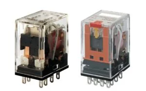
Omron, a very reputed manufacturer of control circuits, medical equipment and industrial automation systems, defines them as follows:
“A relay is a device designed to cause a sudden predicted change in a single or multiple electrical output circuits when certain conditions are satisfied by the electrical circuit that contains the relay device”.
Where do we use relays?
Relays have a wide range of application. You can find them everywhere: home appliances, automobiles, industries, and even in copy machines. In some applications, they are used for switching or control of circuit (as in timer-based lighting control) whereas in others they are used to sense and protect circuits (as in the case of earth fault protection relays). Therefore, it is difficult to specify their area of application area.
Principle of operation
They are basically classified into two types based on their working principle as electro-mechanical and solid-state relays. Let us discuss the principle of operation of each one of them in detail.
Operation of electromechanical relays
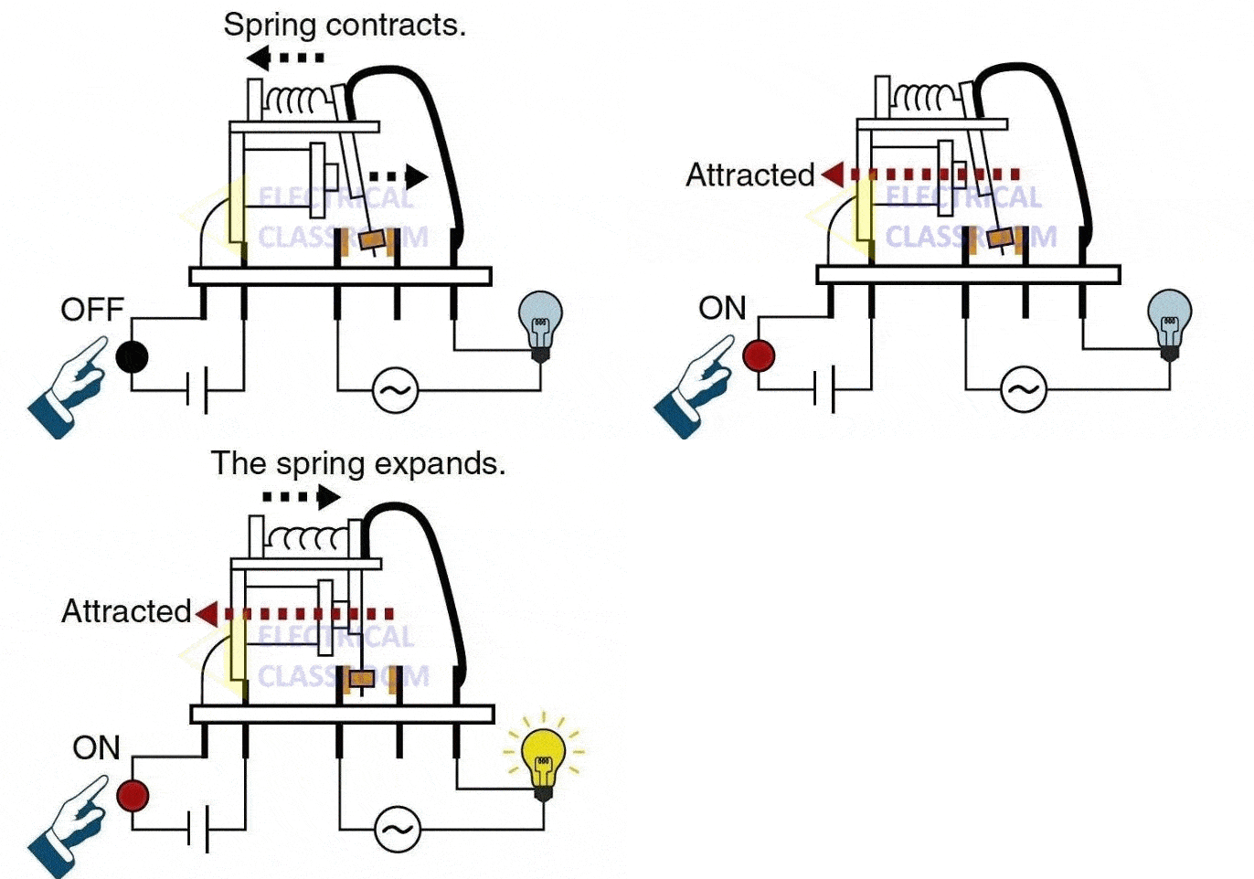
Electromechanical relays transfer signals between its contact through a mechanical motion. It consists of two sections: the first is the electromagnet section and the other is the armature and mechanical contacts section. The electromagnet section consists of a set of coil wound over a magnetic core.
When an input voltage (almost equal to the rated voltage of the coil) is applied to the coil, it gets magnetized and attracts the armature. The mechanical contacts are attached to the armature. Hence, when the armature is pulled towards the electromagnet, the contact closes. When the input voltage applied to the coil is removed, the armature is brought back to its original position by the spring release.
Operation of Solid-state relays
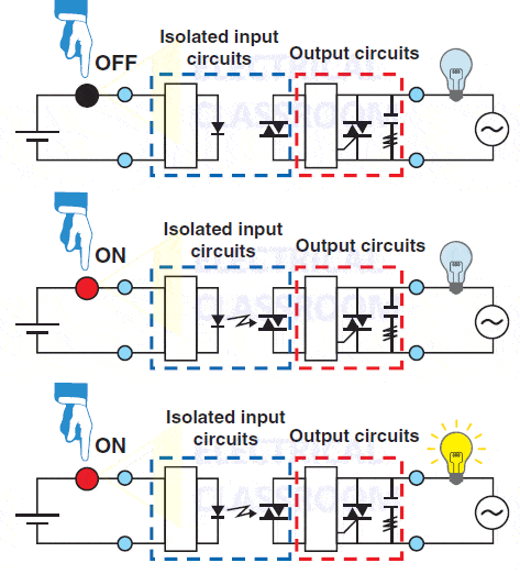
Solid-state relays are commonly known as SSRs. Unlike electromechanical type, they do not posses any mechanically moving parts. On the other hand, it consists of semiconductor and electronic components within. In solid-state relays, the electromagnetic section is replaced by optocoupler and required driver circuits and the output contact section is replaced by a TRIAC or transistor plus snubber and driver circuits.
When the rated voltage is applied to the input section, current flows through the optocoupler. The output of the optocoupler is used to operate the switching circuit of TRIAC or transistor. Switching circuit applies a gate pulse to the TRIAC and the TRIAC starts conducting. Similarly, when the applied input voltage is removed, the optocoupler turns off the TRIAC switching circuit and which, in turn, stops the gate pulse to the TRIAC and the TRAIC stops conducting.
In the following sections, we shall discuss in detail the parts and operation of electromechanical and solid-state relays in detail.
Parts of an electromechanical relay
A typical electromechanical relay consists of the following components:
- Electromagnetic coil
- Armature
- Core
- Movable contacts
- Spring return arrangement
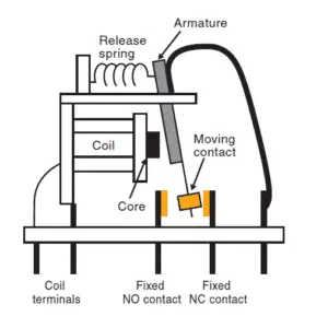
Electromagnetic coil
The electromagnetic coil is the most important part of an electromechanical relay. It consists of a set of copper windings over a magnetic core. As you know, the flow of current through the coil produces a magnetic field. Therefore, when voltage is applied to the coil, it becomes an electromagnet and attracts the armature.
Armature
An armature is a movable piece of metal, balanced using a pivot.
Core
Core is the metallic part over which the coil is wound.
Movable contacts and fixed contact
Contacts are the conducting parts inside the relay, that open or close when voltage is applied to its coil. The contact that is attracted by the electromagnet is called movable contact and that is stationary and connected to the terminals are called fixed contacts.
Spring arrangement
Spring arrangements are also present in them, such as to bring the armature and the contacts back to the original position when the coil is de-energized.
Parts of a solid-state relay
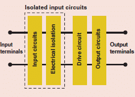
As discussed earlier, solid-state relays do not have any movable parts within. In order to explain their internal parts, here, we have split it to the following sections:
- Input circuit section
- Electrical isolation
- Driver circuitry
- Output section
Input circuit section
The input circuit consists of diodes/transistors/gates and resistors required to drive the optocoupler.
Electrical Isolation
Unlike electromagnetic relays, the input and output sections of an SSR do not have any physical contacts. Galvanic separation is provided between them using optocouplers.
Driver circuit
Driver circuits consist of components required to turn on the TRIAC or transistors or thyristors in the output circuit. The output of the optocoupler is conditioned and the gate pulse needed to trigger the transistor is generated.
Output section
The output section consists of semiconductor devices such as transistor or TRIAC or thyristor as an alternative to relay contacts.
Types of relays
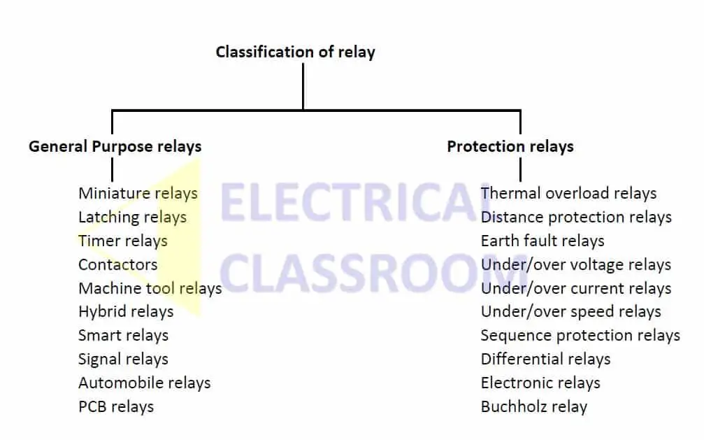
They have a wide range of classifications. Here, we have classified them based on their application as follows:
Classification of relays
Auxiliary or Miniature relays
Auxiliary or miniature relays are those used in the control circuits to switch any device/circuit when some condition is satisfied. It is the basic form of relays, with a coil and a set of contacts for switching. They are available in various contact configurations.
Latching relays
Latching relays hold the position of contacts indefinitely even if the supply to the coil is removed. It consists of two separate coils, one to latch and others to release. When current flows through the first coil (Coil A), the York gets magnetized and the armature is attracted towards the core. The York is made up of a special magnetic material that keeps the armature attracted even if the voltage applied to the coil is removed.
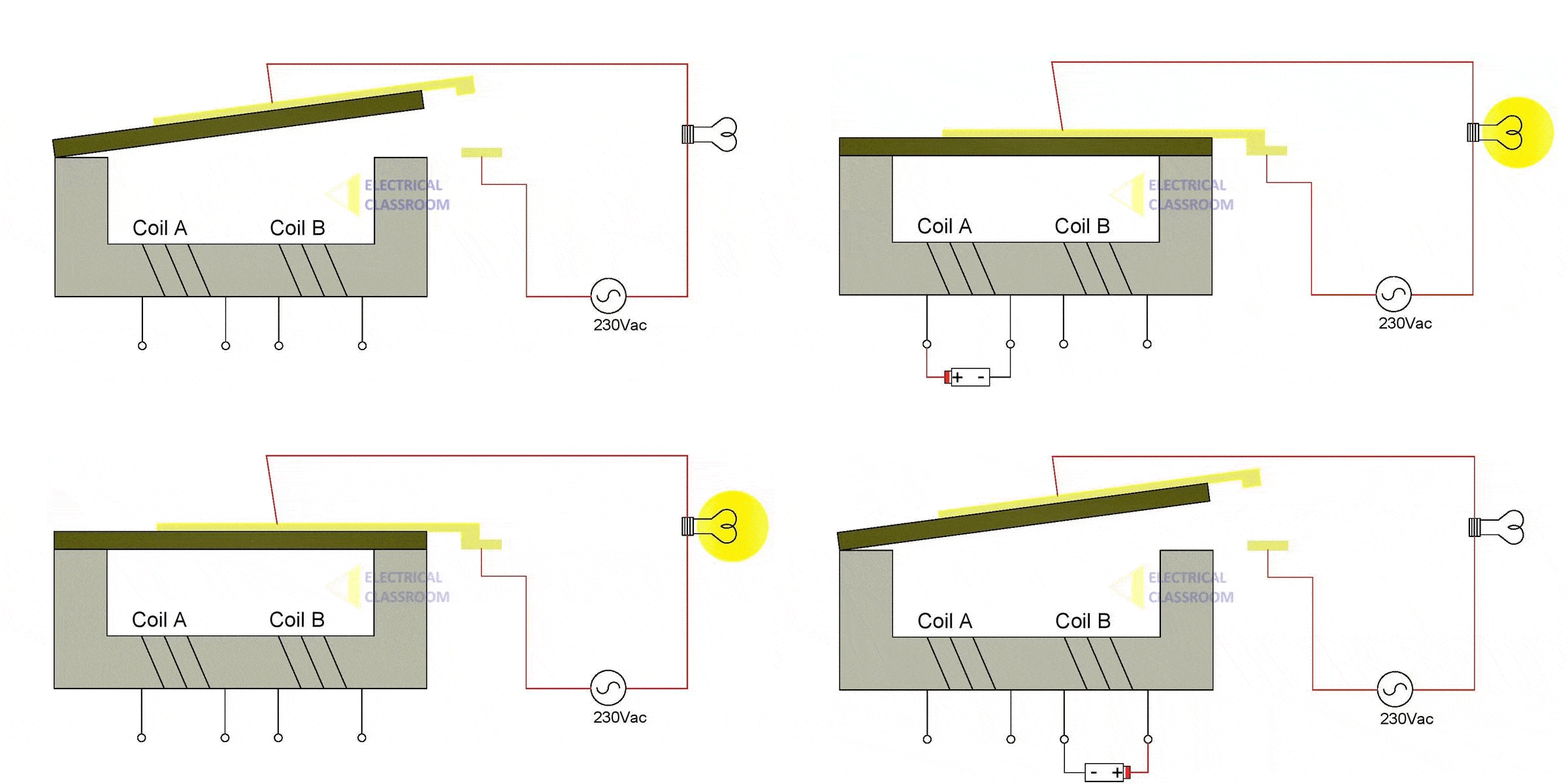
In order to bring back the armature to its original position, voltage is applied to the second coil(Coil B). The second coil is wound over the York in such a way that the current flow through the coil generates magnetic flux opposite to the existing field. This weakens the existing magnetic field and the armature is released. Hence the contacts fall back to its original position.
Timer relays
Delay timers are the example of timer relays. They are made in such a way that the contacts operates in a short time after the coil is energized.
Contactors
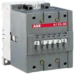
Contactors are used for the switch of electric motors, capacitors, lighting loads and other high-power applications that a relay cannot handle. The principle of operation of contactors is same as that of the relays. Contactors are designed to carry more current than the relays. They have specially designed arc chutes to mitigate the electric arcs formed during the switching of high current loads.
Machine tool relays
These are used for logic control in machinery. These are electro-mechanical relays with a large number of contacts. They are obsolete now and are replaced by PLCs.
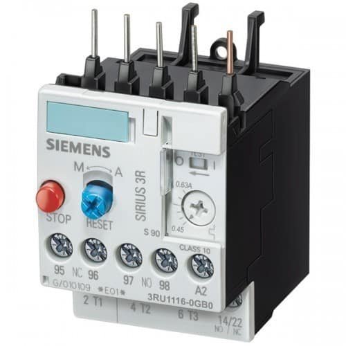
Overload relays
Overload relays are used for the protection of electric motors from overloads and phase losses. They can be either electronic or thermal type. The electronic overload relays use electronic circuits and CTs for sensing current flow to the motor whereas thermal type have bimetallic strips within, that deforms when the current flow through them exceeds the preset limits.
Read More: Overload relay – Principle of operation, types, connection
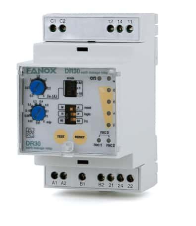
Earth leakage relay
An Earth leakage or earth fault relay (ELR) is used to protect a device or a circuit from earth faults and human being from electric shocks. It senses the current leakage to the earth and helps safely isolating the circuit or device. Their contacts are connected to the trip circuit of a circuit breaker. The ELR activates the trip circuit as soon as the leakage current goes over the preset value and opens the circuit breaker.
Apart from the above classifications, relays are also classified based on the type of operating voltage to be supplied to the coil as DC and AC relays, classified based on construction as sealed, hinged, plunger relays etc.
Read more: Difference between earth leakage and earth fault relays
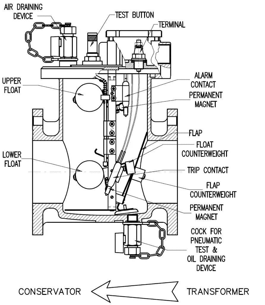
Buchholz relay
Buchholz relay is an oil actuated relay. It gives an alarm or trips the input supply based on the level of oil inside it. It also responds quickly to the unusual oil flow from the transformer main tank to the oil conservator. It is a protection and monitoring equipment not only for transformers but also for oil-immersed chokes with an oil conservator. It protects a transformer from short circuits happening inside the main tank.
Read more: Buchholz Relay – Working Principle, Construction and Operation
Relay contact configuration
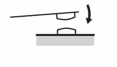
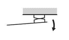
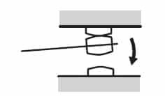
The relay contact configuration is commonly known as ‘relay mechanism‘. Contact mechanisms are mainly classified into three: NC contact, NO contact and transfer contact. NC contacts or break contacts remain closed until the control voltage is applied to their coil and NO contacts or make contacts remain open until the control voltage is applied. Changeover contacts or transfer contacts has a common contact and two other contacts. When voltage is applied to the coil, the contact shift from its original position to the other contact and returns to its previous position when the coil is de-energized.
Symbol
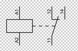
The above figure shows the most commonly used symbol of a relay. A1 and A2 represent its coil and 11, 12 & 14 represent its contacts.
How to use relays in a circuit?
As stated in the principle of operation, relays have two sections: one is the coil and the other is the contact section. It can be controlled by applying a voltage across its coil.
Let’s make a circuit, that can be used to switch a lamp whenever something comes close to it. Here we use a proximity sensor to sense the objects close by. Whenever something comes close to the sensor, it closes the circuit, allowing current flow to the coil. The operating voltage of its coil is 24VDC which is same as that of the proximity sensor and that of the lamp is 230VAC.
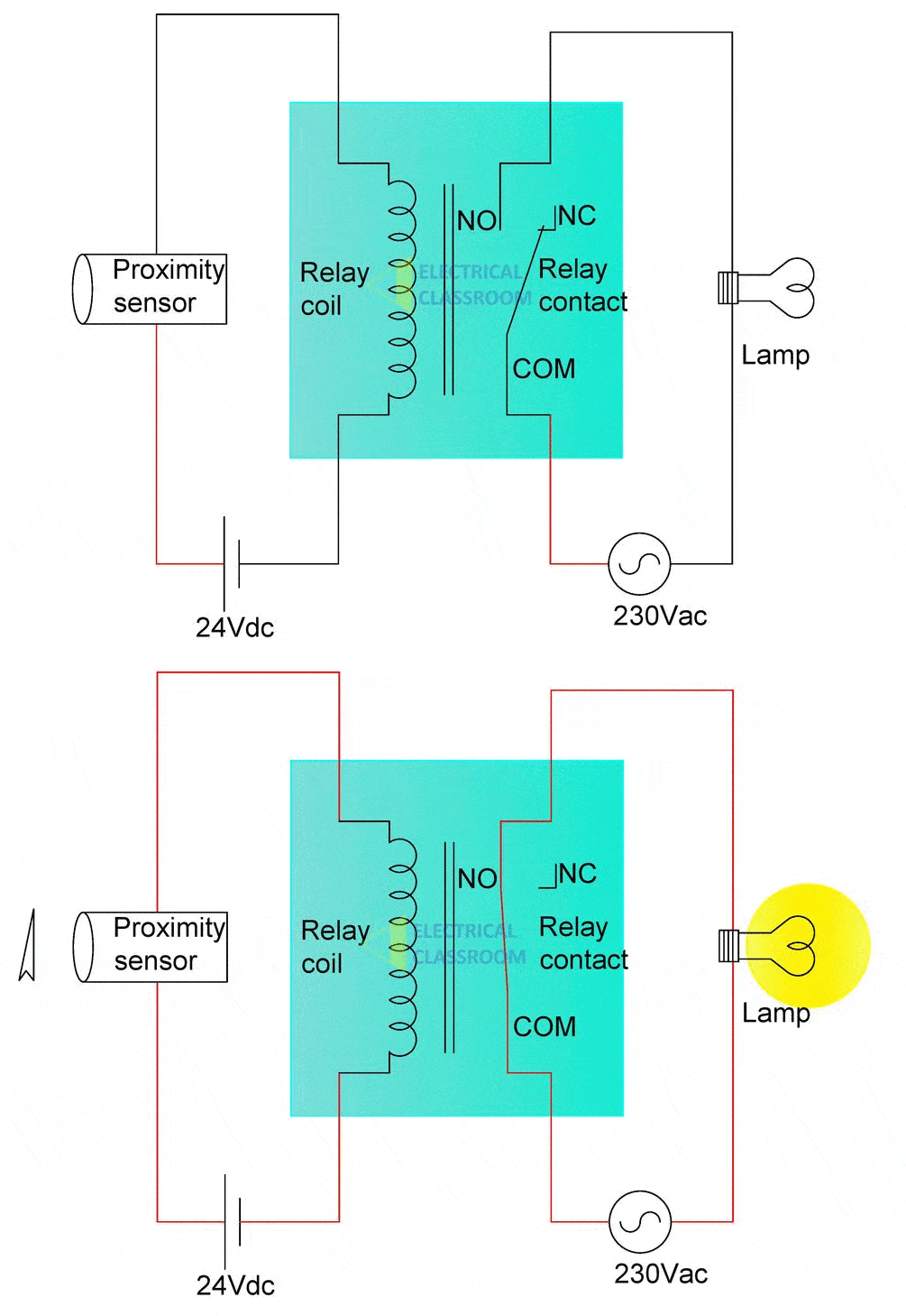
In the above circuit, whenever some object is brought close to the sensor, 24VDC from the source is applied across the relay coil. A current flows through the coil, it is magnetized and the contacts are closed. Therefore, the lamp glows. When the object moves away from the proximity sensor, it stops conducting and the coil is demagnetized, and the contacts fall back to its original position. Current flow to the lamp is interrupted and the lamp stops glowing.
Application
Relays have a wide range of applications starting from washing machines at homes to the telecommunication systems at the International space station, they can be found everywhere. The following are a few key applications:
- They are used in electronic circuits and home appliances for isolating low voltage or DC circuits from high voltage AC circuits.
- They are the backbone of industrial process automation systems. They are used in combination with PLCs for process control. They are one of the key components in an automation cabinet.
- Used for signalling and control in railway networks.
- In motor control circuits for motor switching, protection as well as control.
- In substations and power distribution centers for sensing various faults and operating the circuit breaker.
Relay selection considerations
The following factors must be considered while selecting a relay for any application.
Nominal voltage: The voltage at which the coil is designed to operate.
Rated power: The power consumed by the coil at normal room temperature.
Contact rating: The current carrying capacity and voltage rating of their contacts
Contact mechanism: The number of contacts required and the contact configuration (NO/NC/changeover).
Environmental protection: the degree of sealing required, meaning, whether the external casing of relay is necessary or not?
Insulation resistance: Insulation resistance between any two sets of contacts and that between the contacts and the coil.
Thanks, your write up is really insightful nice and helpful content. Thanks for sharing a helpful article with us.
content is simply nice and how can we use this content. because there is no reference is not mentioned here.
can you please update that
Thanks so much for educating me n relays
Good i have learn something