The below article can guide you through the selection of contactors and overload relays for a three-phase DOL starter and how to optimally size a DOL starter.
- Parameters to be considered during the selection
- Calculation of full load current (FLC)
- Operational voltage and coil supply voltage
- Type of load and duty cycle
- Utilisation categories for contactors according to IEC/EN60947-4-1
- Making and breaking capacity
- Example: Sizing of contactor and overload relay for DOL starter
Data required for the selection of contactor and overload relay
- KW rating of the motor
- Operating voltage
- Application
- KVA code if available
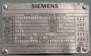
All the above data can be obtained from the nameplate details on the motor.

Parameters to be considered during the selection
- The full load current of the motor
- Operational voltage and coil supply voltage
- Type of load and duty cycle
- Making and breaking capacity of contactor required.
Calculation of full load current (FLC)
Input power to the motor P =√3 V.I.Cosφ kW
Where,
P is rated power of the motor in kW
V and I are voltage and current respectively
From this, we can calculate the full load current of the motor
Full load currrent
Operational voltage and coil supply voltage
- The power contacts of the contactor must be rated not less than the operating voltage of the motor(as per nameplate details).
- The coil voltage/control voltage of the contactor must be determined based on the control circuit design.
Type of load and duty cycle
- IEC 60947-5-1 defines the requirements for electromechanical devices for control circuits.
- It indicates the type of electrical load and duty cycle of the loads to ease the selection of contactors and relays.
Utilisation categories for contactors according to IEC/EN60947-4-1
| Utilization category | Typical application |
|---|---|
| AC-1 | Non-inductive or low-inductive load, resistance furnaces |
| AC-2 | Slip ring motors: starting, switching off |
| AC-3 | Squirrel cage motors: starting, switching off while running |
| AC-4 | Squirrel-cage motors: starting, regenerative braking, reversing, jogging |
Making and breaking capacity
The making/breaking capacity of a contactor is the maximum current that it can make or break safely. It must be equal to or greater than the locked rotor current. The locked rotor current can be calculated using the following formula:
Locked rotor currrent
(KVA/HP) is indicated on the nameplate details of the motor-based NEMA code.
| NEMA Code Letter | kVA/HP with locked rotor | Approximate Mid-Range Value |
|---|---|---|
| A | 0 – 3.14 | 1.6 |
| B | 3.15 – 3.55 | 3.3 |
| C | 3.55 – 3.99 | 3.8 |
| D | 4.0 – 4.49 | 4.3 |
| E | 4.5 – 4.99 | 4.7 |
| F | 5.0 – 5.59 | 5.3 |
| G | 5.6 – 6.29 | 5.9 |
| H | 6.3 – 7.09 | 6.7 |
| J | 7.1 – 7.99 | 7.5 |
| K | 8.0 – 8.99 | 8.5 |
| L | 9.0 – 9.99 | 9.5 |
| M | 10.0 – 11.19 | 10.6 |
| N | 11.2 – 12.49 | 11.8 |
| P | 12.5 – 13.99 | 13.2 |
| R | 14.0 – 15.99 | 15.0 |
| S | 16.0 – 17.99 | |
| T | 18.0 – 19.99 | |
| U | 20.0 – 22.39 | |
| V | 22.4 – and up |
Example: Sizing of contactor and overload relay for DOL starter
Let us calculate the contactor and overload rating for DOL starter of the following motor:
7.5KW(10HP), Three-phase squirrel cage induction motor, 415 volts, 50Hz, 1450rpm, the efficiency of the motor: 90%, pf: 0.85, KVA code: H
Full load currrent
Locked rotor currrent
Hence, Contactor must rating must be AC-3 duty with a current rating more than 12.28A and making breaking current more than or equal to 102A.
Selection of thermal overload relay
Min. Thermal Overload Relay setting = 70%x Full Load Current(Phase)
Min. Thermal Overload Relay setting = 70%x12.28 = 8.6A
Max. Thermal Overload Relay setting = 120%x Full Load Current(Phase)
Max. Thermal Overload Relay setting = 120%x12.28 = 14.7A
Hence, Overload must be chosen closer to the range of 8.6-14.7.
The right selection of contactor and overload relays is necessary to start a motor safely. The above calculations can help you select the optimal rating of contactors and overload relays. Learn more about the operation of contactors, overload relays, and star-delta starters from the following article. You can also use the DOL starter selection tool and Star-Delta starter design tool | Wye-Delta starter design tool for the selection of contactor and overload relays.
For selection of thermal overload 70% for min and 120% for max is chosen.
Please provide the reference.
per NEC it is 125% of the full load current sizing a separate overload relay (not integral with the motor)
thanks for providing useful information on Sizing of contactor and overload relay for 3 Phase DOL starter
Very useful information. Thanks
very helpful information,thanks
Thank you Oscar
Hi information given is much more interesting thanks you