Induction motors are robust and reliable and are used in all industries across the globe. Various methods are followed to start induction motors, out of which star-delta starters are the most commonly used ones to reduce the starting current. Star-delta starters are cheaper than soft-starters and are widely seen in small-scale industries. Typically, star-delta starters are used for motors rated above 5kW. Here you can learn the fundamentals and operation of star-delta starters.
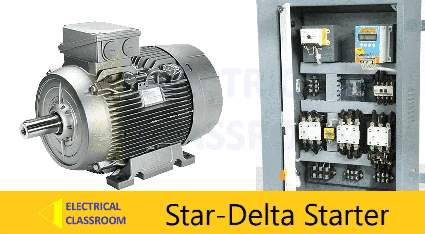
When an induction motor is started directly online, it tends to draw a starting current ranging between 6 to 10 times its normal full load current. It can result in voltage sags. A star-delta starter can help to reduce this starting current by 33%.
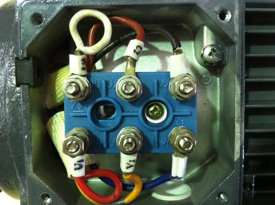
Note: In order to start a motor using a star-delta starter, both ends of each of the three windings of the motor must be brought to the terminal box as shown below:
Parts of a star-delta starter
A star-delta starter consists of the following parts.
- Fuse or circuit breaker – For short circuit protection.
- Contactors – For switching.
- Star-delta timer – to switch between star and delta connection.
- Overload relay- For overload protection.
Try: Star-Delta starter circuit design tool
Working of star-delta starter
Power circuit
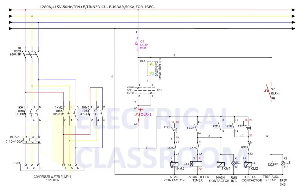
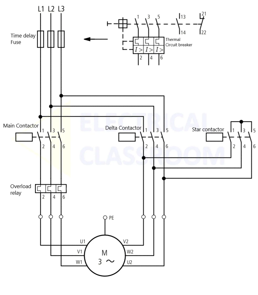
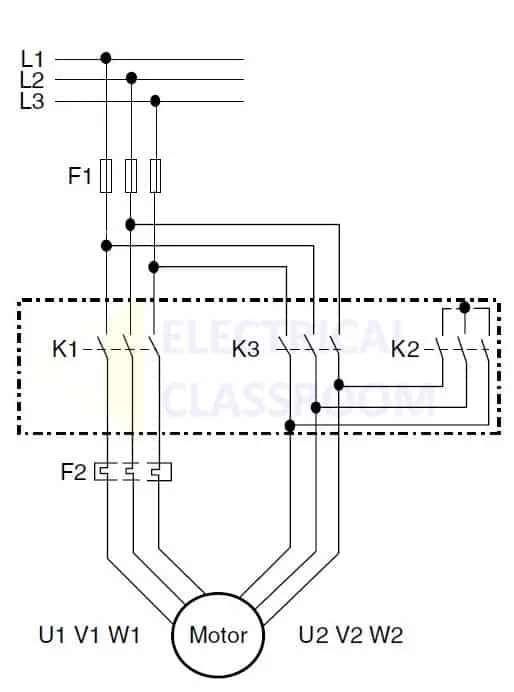
Figure 1 shows the circuit diagram of a typical star delta starter. As mentioned earlier, apart from protection fuses (F1), and overload relay (F2), the circuit consists of three contactors – a line or main contactor (K1), a delta connection contactor (K2), and a star connection contactor (K3). The terminals (U1, V1, W1) are connected to K1 through F2 & (U2, V2, W2) K2 and K3.
During start-up, K1 and K2 are closed to connect the winding in a star configuration. After a time delay, K2 is opened and K3 is closed to connect the windings in the delta configuration. When connected K2 is closed, the phase voltage is applied across the motor terminals.
Let’s calculate the starting current reduction achieved using the star-delta starter:
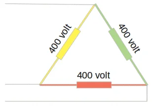
For a delta connection,
VLine = Vphase
So the applied voltage is equal to the voltage measured across the winding. But the current varies as below:
ILine = 1.743 x Iphase
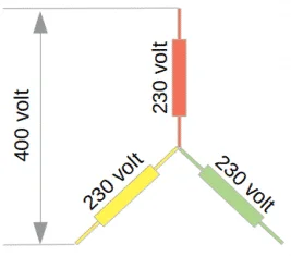
For a delta connection,
VLine = 1.743 x Vphase
(i.e.) Vphase = 0.577 x VLine
The voltage measured across each winding is 0.57 times the applied voltage. But the line and the phase currents remain equal.
ILine = Iphase
Lets consider a motor having a winding impedence of 10ohms. Let 400V be the voltage applied across the winding.
When in delta configuration,
VLine-delta = Vphase-delta = 400V
Iphase-delta = 400/10 = 40A
ILine-delta = 1.743 x 40A = 70A – (Result-1)
When in the star configuration,
VPhase-star = 0.577 x VLine-star = 230V
Iphase-star = 230/10 = 23A
ILine-star = Iphase-star = 23A – (Result-2)
Comparing Result-1 and Result-2:
ILine-delta / ILine-star = 70A/ 23A = 3
(i.e.) ILine-delta = 3 x ILine-star (or) ILine-star = 0.33 x Line-delta
From the above calculation, it is evident that the starting current flow from the mains while in the star configuration is one-third of that in the delta configuration.
Control circuit
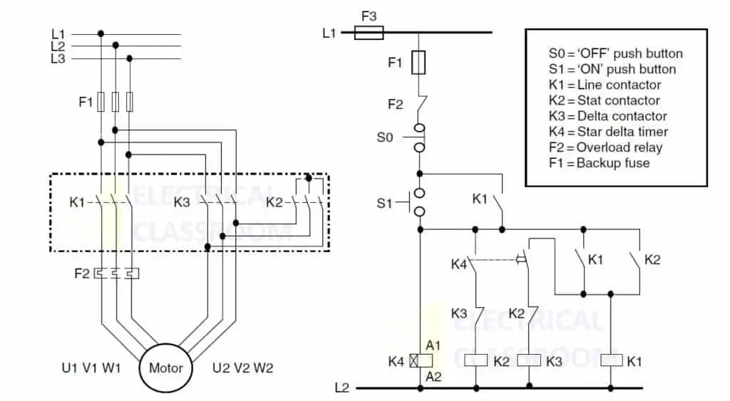
The control circuit controls the switching of contactors and the transition from star to delta configuration. A typical circuit consists of a fuse, start(S1) and stop (S0) pushbuttons, star-delta timer (K4), and auxiliary contacts of overload relay and contactors.
Under normal conditions (F1, F2, and F3 are healthy), when S1 is pressed, timer coil K4 will pick up and it energizes the coil of the contactor K2, and that in turn energizes the coil of line contactor K1. This will drive the motor in the star configuration. The NO contact of K1 is wired parallel to S1 such that the circuit remains latched until S0 is pressed.
After the time duration is set on the star delta timer, the K2 coil is de-energized and K3 is energized and the motor runs in the delta configuration. When S0 is pressed or during overload trips or the F1 fuse blown-outs, the coils of the contactor K1 and K3 de-energize and the motor stops.
Star contactor (K2) and Delta contactor (K3) are electrically interlocked using NC contacts, such that both contactors are never closed at a time. Additionally, they are also mechanically interlocked. This makes sure that the coil of K2 is energized only when K3 is open and the coil of K3 is energized only when K2 is open.
Torque reduction
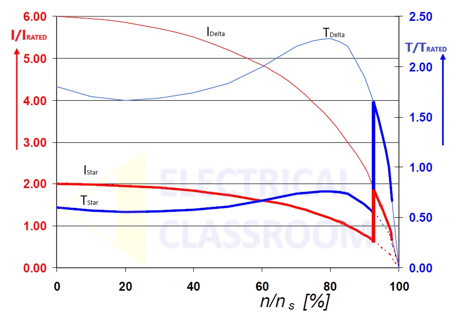
Since the starting current is reduced by the factor of three, the starting torque also reduces by the factor of 3. The characteristics of current and torque during start, run and transition from star to delta are shown in the figure below.
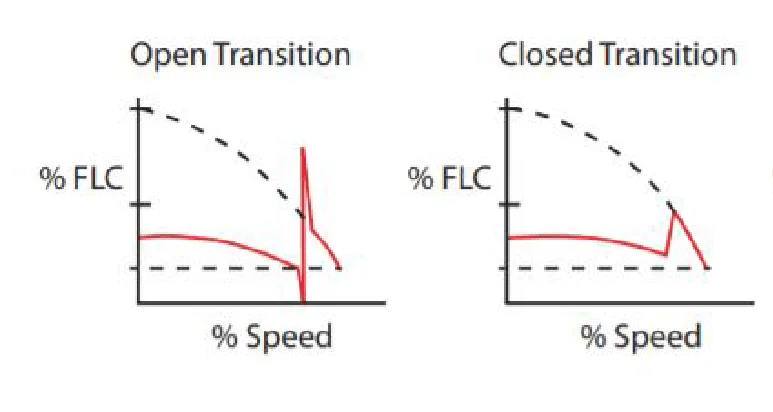
The transition from star to delta can be an open transition or a closed transition.
Open transition star-delta starting
The circuit that we discussed earlier (Figure 1A) is that of an open transition star-delta starter. If you closely observe, the motor is disconnected during the transition from star to delta configuration. Meaning that the starter momentarily disconnects from the motor and reconnects in a delta configuration.
The transition may result in transient currents and torque dependent on the magnitude of back EMF generated by the rotor at the instant of the closure of the delta contactor. It is easier, cost-effective, and widely used than the closed transition starting.
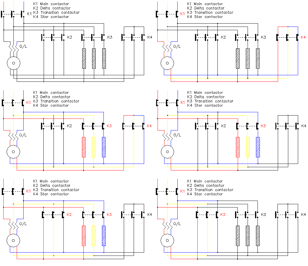
The following are the four stages of open transition starting:
- Off Stage
- Star stage
- Transition Stage
- Delta stage
The open transition from star to delta comes with a disadvantage. Depending on the motor load and transition interval, the resulting surge in current and torque could produce electrical and mechanical shocks in the system. In some cases, the instantaneous current peaks can exceed even the locked rotor current for short durations. In many applications, the time the motor to accelerate the load to full speed is crucial. The Closed transition star-delta starting can be used in places where we need to eliminate surges.
Closed transition star-delta starting
In closed transition, the transition from the star to delta configuration is achieved without disconnecting the motor. In order to achieve that, an additional three-pole contactor and three resistors are required. This contactor is closed before opening the star contactor and opened after closing the delta contactor. By doing so, the transition current can be limited.
The following are the stages of open transition starting:
- Off State
- Star Stage – Main contactor and Star contactor will be closed.
- Transition state – Transition contactor is closed and star contactor is opened.
- Delta stage – Delta contactor is closed and transition contactor is opened.
Advantages and disadvantages of star-delta starters
Advantages
- The cheapest method to start a motor.
- The starting current is reduced to 33% of direct online starting current.
- Better torque per ampere of line current than other starters.
- Star-delta starters do not require any voltage reduction equipment.
- In open transition no heat is produced.
- The size of the overload relay can be reduced to 50%.
Disadvantages
- Due to current reduction, torque is also reduced to 1/3 of direct online starting torque.
- Six terminal motor required.
- Break-in supply to the motor during the transition from star to delta.
- More cable is required.
sound & clear explanation
In delta connection U1 should be connected to W2, and in your diagram U1 connected to V2.
and the other is Vline = 1.73 × Vphase, therefore, Vphase = Vline ÷ 1.73 again you are wrong.
Very well explained.
At calculation, U were mentioned VLine-star = 0.577 x Vphase instead off
Vphase = 0.577 x VLine wrongly…
Thank you for notifying us. That was a great observation. We have corrected the formula now.
Good class! . Please how can I calculate the time transition from star to delta in open transition. Or in closa transition, how can I calculate the value of three resistors.
Current transformer question. Where would one place Current Transformers (CT) to measure the current draw on the load side of the Wye/Delta starter relays when the line side off limits? T1, t2, and T3 or T1&T6, T2&T5, and T3&T5? On a duel voltage motor wired for low voltage (Delta connection), CTs would be measuring T1&T6, T2&T5, and T3&T5. Wouldn’t that be the same?