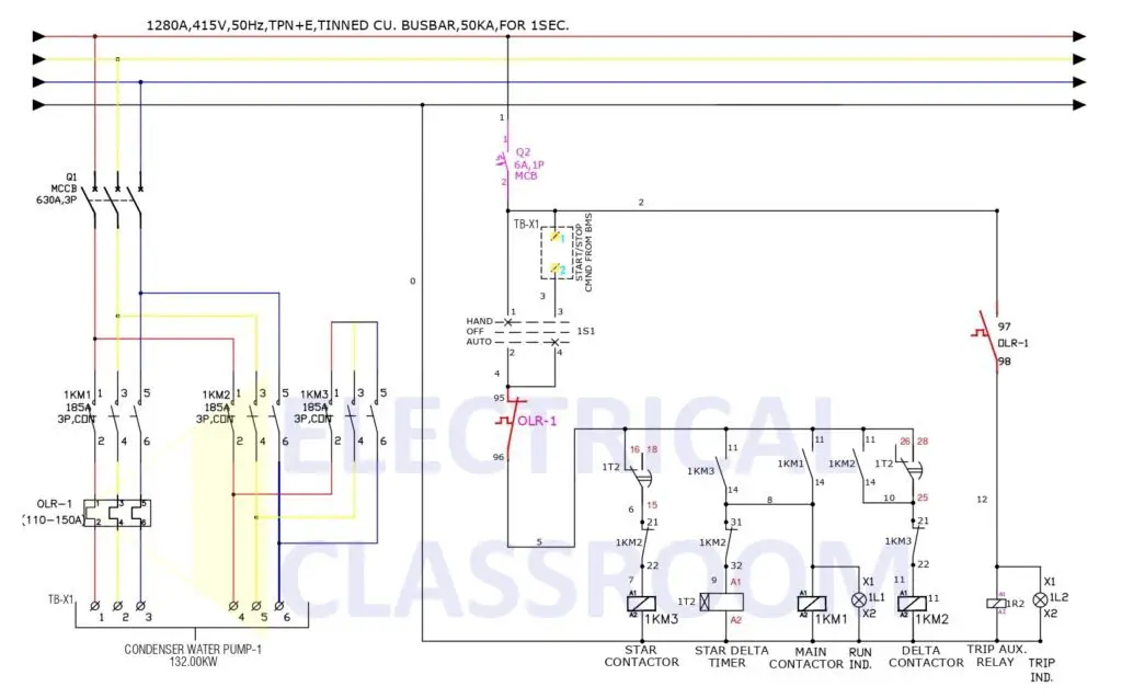
The power and control circuits of a star-delta starter are discussed in this article with the help of an actual star-delta starter wiring diagram. You can find the instructions to calculate the ratings of contactors for a star-delta starter circuit here: Star-Delta starter design tool. Further operation in detail can be found here: Star-delta starter (Wye-Delta Starters) – Circuit, working.
Star-Delta starter wiring diagram
The wiring diagram for a 132kW star-delta starter used for a condenser pump is shown below:

The diagram can be divided into two parts: The power circuit & control circuit.
Power circuit wiring
The power circuit of the starter consists of the following components:
- MCCB (Q1) : Protects the circuit from short circuits.
- Contractors : Main (1KM1), star (1KM2) and delta (1KM3). For switching.
- Overload relay. (OLR1) For protection against overloads.
- Terminals. (TB-X1) For motor connection.
Control circuit wiring
The control circuit of the starter consists of the following components:
- MCB (Q2): For circuit protection.
- Operation mode selection switch (1S1). For selecting the mode of operation. When turned towards hand mode, the starter is triggered immediately and when turned towards auto, the circuit is triggered only when an external command is received from BMS/PLC/DCS.
- Coil and auxiliary contacts of Main (1KM1), star (1KM2) and delta (1KM3) contactors.
- Star delta timer (1T2): Timer that switches the star and delta contactors.
- Indication lamps (1L1, 1L2): For starter status indications.
Circuit operation
When the selector switch 1S1 is turned towards hand and the overload relay is not in trip position, the star contactor 1KM3 is turned on instantaneously, The timer IT2 and the main contactor 1KM1 are now turned on through the auxiliary contact of 1KM3. After a time delay, the timer auxiliary contacts 15-16 changes over to 15-18, thereby opening 1KM3 contactor and after a very short delay, the timer auxiliary contacts 25-26 changes over to 25-28, and the delta contactor 1KM2 is closed, thereby completing the star delta transition.
When the selector switch is turner towards auto position, the above mentioned sequence will start when start command is received from the BMS between the terminals TB-X1: 1 and TB-X1: 2.
On the occurrence on motor overload, OLR-1 contacts 95-96 opens, thereby tripping the entire circuit.
The run indication 1L1 turns ON along with main contactor and the trip indication 1L2 turns on when the OLR trips.
star delta control digram
The app is very good and easy to understand.
thanks alot