Circuits can contain many power sources and power dissipation elements. It is common that any one of the elements in the circuit is a variable while all others are fixed. Thevenin’s theorem is applied in order to simplify complex circuits with a single varying load. Confused? Let us discuss a very common example:
Imagine the utility socket in your home. Each appliance in your home has a different impedance. So, every time you plug in an appliance to the socket the load added to the circuit is different. Whereas the other circuit remaining parameters such as wire resistance remain constant at normal temperature. Hence, the circuit needs to be analyzed each time a different appliance is plugged in.
To avoid this problem, Léon Charles Thévenin came up with a new approach of circuit analysis, by which the fixed elements of the circuit can be replaced by their equivalent.
- Thevenin’s theorem statement
- Solved examples
- How to find thevenin’s resistance?
- How to find thevenin’s voltage?
- Steps to calculate Thevenin’s equivalent circuit
- Summary
Thevenin’s theorem
Thevenin’s theorem states that any linear network having a number of voltage sources and resistances can be replaced by a simple equivalent circuit consisting of a single voltage source (VTH) in series with a resistance (RTH), where VTH is the open-circuit voltage at the terminals of the load and RTH is the equivalent resistance measured across the terminals while independent sources are turned off.
Simply, Thevenin’s theorem states that any linear network with several power sources, resistances and a variable load can be represented in a much simpler circuit containing a single voltage source (VTH) (known as Thevenin’s equivalent voltage) in series with a resistance (RTH) (known as Thevenin’s equivalent resistance) and the variable load, where VTH is the open-circuit voltage at the terminals of the load and RTH is the equivalent resistance measured across the terminals while independent sources are turned off. See the below figure for better understanding.

Solved examples
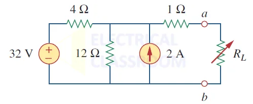
Thevenin’s theorem can be better understood from the below example:

Problem: Let’s find the Thevenin’s equivalent circuit for the above circuit.
Solution
In the above circuit, we have a voltage source (32V) and another current source (2A).
Step 1: Find Thevenin’s resistance
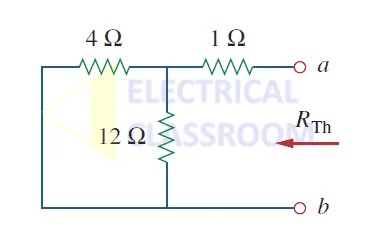
While calculating the thevenin’s equivalent resistance, all voltage sources must be turned off, meaning it acts like a short circuit and all current sources act like an open circuit, as shown in the figure below:

Let us calculate the thevenin’s resistance for the above circuit:
Thevenin’s resistance, Rth = 4 || 12 +1 = 4 x 12 / 16 + 1 = 4 ohms
Step 2: Find Thevenin’s voltage
Let’s perform mesh analysis to find Thevenin’s voltage:

4i1 + 12(i1 – i2) = 32V, i2 = -2A
Solving the above equations, we get i1 = 0.5A
Therefore Vth = 12(i1 – i2) = 12(0.5 + 2) = 30V
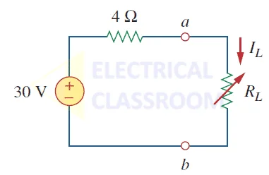
Step 3: Draw equivalent circuit
The equivalent Thevenin’s circuit is shown in the figure below:

Steps to calculate Thevenin’s equivalent circuit.
- Remove the load resistance.
- After short circuiting all the voltage sources and open circuiting all current sources, find the equivalent resistance (Rth) of the circuit, seeing from the load end.
- Now, find Vth by usual circuit analysis.
- Draw Thevenin’s equivalent circuit with Vth, Rth and load. From this circuit we can calculate IL for different values of load resistance.
Summary
Thevenin’s theorem is very important in circuit analysis, power system analysis, short circuit calculations and is a key tool for circuit design. Thevenin’s circuit is a simplified form of a large circuit containing multiple power sources and resistances. The simplified circuit contains a voltage source (equivalent to the voltage measured across the terminals of the load) and an equivalent resistance in series with the variable load.
Marvellous
What about situations where there are three other resistors on the loop the Vth is on the circuit?
amazing
amazing
Great
Good job, well done!
great
Thanks