A transformer core serves the following three important purposes:
- Provides mechanical support to the windings.
- Provides a low reluctance closed ferromagnetic path to the magnetic flux.
- Reduces the losses due to flux leakage.
The primary and secondary windings of a transformer are wound over the core but physically separated from each other. The transformer core is designed to magnetically link the windings and also to provide low reluctance path for the magnetic field. Also, the core must be designed in such a way to minimize the eddy current losses and hysteresis losses. On the contrast, the core acts as a coupling between the windings.
Transformer core material
The following factors affects the selection of core material:
- Maximum magnetic induction.
- Minimum specific core-loss for low no-load loss.
- Low reluctance to magnetic flux.
- Low apparent power input.
- Low magnetostriction for minimal noise.
- Good mechanical strength to hold the windings.
The transformer core is made up of thin laminations of cold-rolled grain-oriented silicon steel (CRGOS), commonly known as core steel. The core steel is made by alloying silicon with low carbon content steel. The transformer cores made from CRGOS has high permeability. High permeability subsequently reduces magnetizing currents and core losses. Moreover, silicon steel has aging effects compared to non-silicon steel.
In addition to the above, the CRGOS cores are manufactured by cold rolling which changes the orientation of the grain in the direction of rolling. The flow of magnetic flux in the direction of grain orientation will reduce the flux losses in the core, thereby reducing the iron losses. The problem with the cold rolling is that when the flow of flux is other than the direction of the grain orientation, will result in increased core losses. In addition, mechanical stresses, limb joints, and bolt holes also affect core losses.
The lamination of transformer core is made up of cold rolled grain oriented steel at a thickness ranging between 0.18mm and 0.35mm. Based on the grain orientation, the lamination is classified into conventional grain-oriented and HI-B steels. Further HI-B steel has low watts/kg when compared to CGO steel. As the eddy currents highly depend on the thickness of the sheets and the frequency of the alternating current, thinner sheets are always prefered for core construction.
On the other hand, reducing the thickness of sheets degrades the stacking factor. Deburring the sheets and annealing them at 800-900 degrees Celsius in natural gas environment improves the stacking factor and minimizes the eddy current losses. The laminations are generally passed through hot steel slabs that squeeze them to thin sheets. Also, both sides of the sheets are coated with Carlite, in order to insulate them from the adjacent sheets.
Construction of transformer core
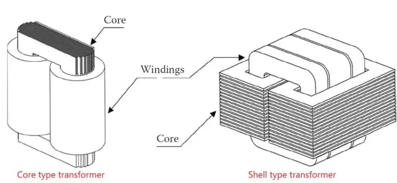
The vertical part of a core on which the windings are mounted is known as Limbs and the horizontal part that connects the limbs is known as yoke. Depending on how the primary and secondary windings are arranged transformers are classified into two:
- Core type transformers
- Shell type transformers
Core type transformers
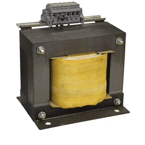
In core type construction, the primary and secondary winding are wound around the transformer limbs. The low voltage windings are placed closer to the core and the high voltage windings surround them.
Single phase core type transformers
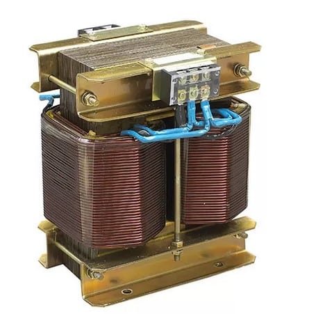
This type of transformer consists of a rectangular core with two limbs and two yokes. The primary and secondary windings are split into two parts and placed around either limbs. The cross-sections of limbs and the yokes are kept identical. The leakage flux in this type of cores is higher due to the distributed nature of the windings.
Three phase core type transformers
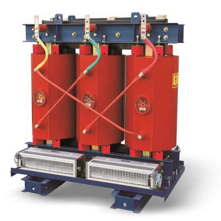
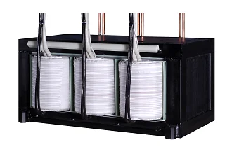
This type of transformers have three limbs and two yokes at its core. They are generally used for three phase transformers of small and medium power ratings. Each phase is wound around each legs of the transformer. The algebraic sum of the magnetic fluxes induced by the phases remains zero at any instant of time time.
Shell type transformer cores
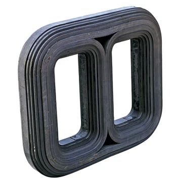
In shell transformers the windings encircles the middle limbs and the outer limb surrounds the windings inorder to ensure better flow of magnetic flux.
Single phase shell type transformers
In single-phase shell-type transformers the windings are wound around the central limb of the core. The magnetic flux flows through the auxiliary limbs. The auxiliary limbs and yoke need to be half the cross-section of the central limb. This type of construction is preferred over the core type construction, as this is more economical than the other.
Three phase shell type transformers
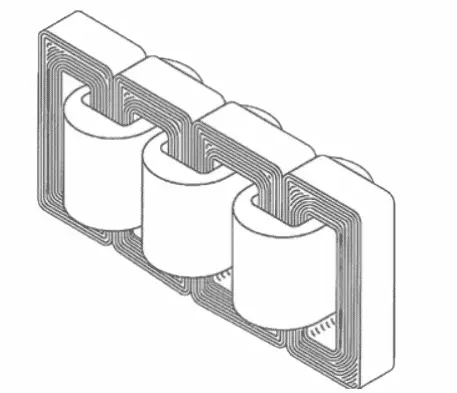
The core of three-phase shell type transformer has 5 limbs. The primary and secondary windings are wound around three inner limbs, one set of primary and secondary windings per phase per limb. This type of construction can help in reducing the height of the core. The limb and yoke diameters can have several configurations. The most commonly found arrangements are as follows:
- Cross sections of all yokes can be equal amounting to 50% of cross section of the limbs.
- The cross section of all inner yokes will be 58% of inner limbs and that of out yokes will be 45% of the inner limbs.
- The cross section of yokes and the outer limbs are reduced to 40% of the cross section of the limbs.
Wound core and stacked core construction
As mentioned earlier, a transformer core is constructed by combining thin steel sheets (laminations). These laminations can be either wrapped around the coil or stacked.
Wound core construction.
In order to manufacture a wound core, the CRGOS sheets are cut in form of a hollow rectangle or the shape of the entire core itself. These laminations are then stacked together to form a core. The core is then cut so that it can be inserted through the coils. The cut-core is then reassembled to form a step type of joint. Wound cores have fewer joints compared to stacked core constructions. Therefore they can carry the flux through them nearly uninterrupted.
Wound cores are commonly used in the construction of distribution transformers rated between 25 kVA and 2500 kVA.
Stacked core construction
In stacked core construction, the laminations for each yokes and limbs are cut separately and then combined together to formed the core. The stacked cores have gaps at the corners where the yoke and the limbs join. These gaps results in poor magnetic characteristics when compared to wound core construction. The core can be circular or rectangular in shape. For single-phase, transformers rated below 5MVA and three-phase transformers rated below 10MVA the cross-section of the core can be rectangular or circular. For all other transformers rated above that, circular cross-sections are preferred to maximize the flux carrying area.
In both constructions laminations are coated with insulationing substances to reduce eddy current losses. The following videos shows the manufacturing process of stacked core.
Corner joining of Limbs and Yokes in stacked transformer core
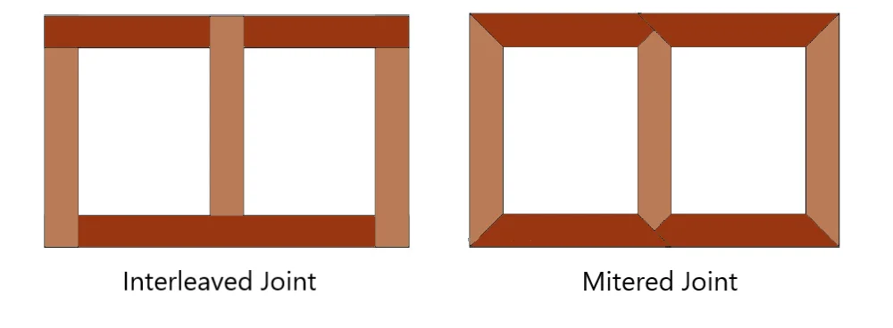
The following are the two most commonly used corner joining methods: (a) Interleaved joining (b) mitered joining.
Interleaved Joint
Interleaved joints are made by placing limbs and yokes overlapped at their ends as shown in the figure. This is the simplest form of joint. Due to their poor magnetic characteristics and they are comparatively less efficient than the mitered joints. Such joints are preferred for small transformers only.
Miltered Joints
The figure below shows mitered joint. The joining laminations are cut at an angle of 45o so that the flux in the turning corner will pass through the right angle bend at a minimum loss. In such joints, the magnetic flux can smoothly enter and leave the bends. The manufacturing cost can be slightly higher than interleaved joints.
Relationship between core diameter and kVA
The basic parameters of a transformer core are core diameter, yoke height, limb length, and limb center. The relationship between the transformer KVA (S) and core circle diameter (D) is given by the following formula:
D = k(S)1/4
Where k is a constant depending on the type of the transformer.
Learn more about design aspects of core: http://actaenergetica.org/article/en/design-of-transformers.html
Losses in transformer core
The losses occurring in a transformer core are commonly known as no-load losses. These losses are caused due to hysteresis of the core and the eddy currents induced in the core. To know more about these losses refer: Hysteresis loss and Eddy current loss and their difference.

Nice post