Tap changers are voltage regulation equipment used to adjust the voltage ratio in transformers by adding or removing tapping turns. Voltage adjustments can be made by using either on-load tap changers or off-load tap changers. Taps can be made either on the primary or the secondary of the transformers. It is important to maintain the system voltage with certain limits for proper functioning and better health of all equipment connected to the system.
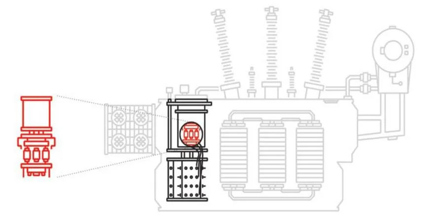
In the intricate landscape of modern electric power systems, transformers find a multitude of applications, ranging from generator step-up and system interconnection to distribution, arc furnace operation, and HVDC converters. Essentially, transformers serve the pivotal function of converting electrical energy from one voltage level to another. As power systems evolve to become larger and more complex, power transformers emerge as key players, profoundly influencing the efficiency and stability of the entire system.
Each transformer integrated into a network is associated with an ideal voltage ratio, a critical parameter for ensuring optimal system operation. Unfortunately, determining this optimal voltage ratio proves challenging as it dynamically shifts based on the operational conditions of the entire network. Recognizing this variability, early pioneers in the field of electric power systems realized that for seamless and satisfactory operation, transformer voltage ratios needed adjustability without disrupting the continuous flow of energy. This necessity led to the development of Load Tap Changers (LTCs).
Why are tap changers required in transformers?
Tap changers are required for the following reasons:
- To compensate regulation within the transformer and maintain a nearly constant output voltage.
- To compensate voltage changes in the system.
- To assist in the control of VAr flows.
In-tank Tap Changers (Jansen Type):
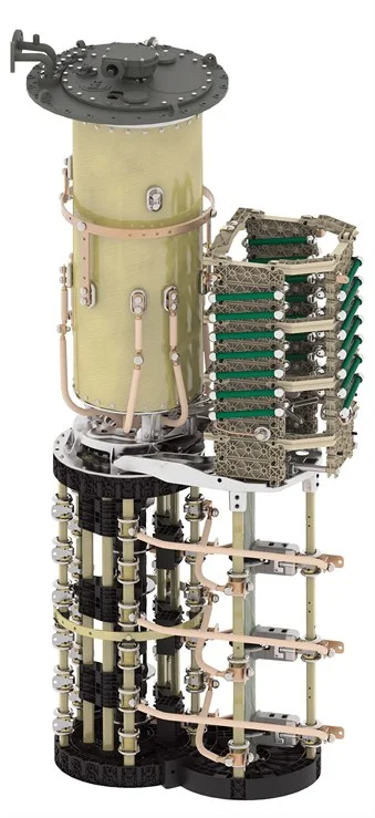
The in-tank tap changer, colloquially known as the Jansen type, constitutes a comprehensive solution residing within the main transformer oil alongside the core-and-coil assembly. Positioned at the bottom of the tap changer, its selector and changeover switches orchestrate crucial adjustments within the main oil. Notably, the arcing (diverter) switch finds its home in a distinct compartment at the top, often enclosed within a sealed cylinder crafted from materials like fiberglass. This design confines all arcing activities to this compartment, ensuring enhanced safety and reliability.
Configurations of this type are available in both single-phase and three-phase neutral end Wye (Y)-connected versions. For three-phase fully insulated applications, the deployment of three single-phase tap changers becomes imperative. This type excels in applications demanding higher voltages or current levels.
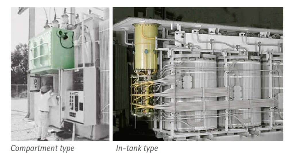
Separate Compartment Tap Changers:
Diverging from the in-tank design, the separate compartment tap changers stand as distinct entities assembled independently from the transformer. Secured to the side of the transformer tank and linked to the tapped windings through a connecting board, they are placed in their own compartment, isolating their selector, changeover, and arcing switches from the main transformer oil.
Some variants feature dual compartments, segregating the arcing switch from the selector and changeover switches. Others streamline these components into a singular compartment. These are available in three-phase assemblies, catering to Wye-connected configurations for applications at the neutral end of a three-phase transformer, or fully insulated setups suitable for applications at the line end.
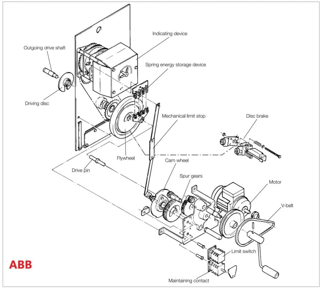
Motor-drive mechanism
A Motor-drive mechanism is used to change the taps in a transformer in modern transformers. This mechanism uses a set of gears and a spring energy storage unit, which, when completely charged, uses a drive shaft to turn on the tap-changer.
Below is the circuit diagram for ABB’s OLTC drive mechanism:
Tap changer types
Primarily, they are classified into two types:
- Off-load or No-load tap changers (NLTC)
- On-load tap changers (OLTC)
Working principle of No-load tap changers (OFTC)
Off-load or no-load tap changers are used in application where the tap change is not required very frequently. Tap changing requires the insolation of load from the transformer. They are commonly used in dry transformers, since dry transformer doesnot have oil to quench the arc.
Working principle of on-load tap changers (OLTC)
Since the tap changing happens while on-load, the switching from one tap to another must occur without interrupting the current flow to the load, at the same time no short circuits should happen during the switching.
Hence the tap changing must follow a make-before-break sequence. During the make before break interval, there there must be something to prevent the shorting of the turns. Two ways are primarily used to accomplish this: using resistive switching or using reactive switching.
Resistive Switching
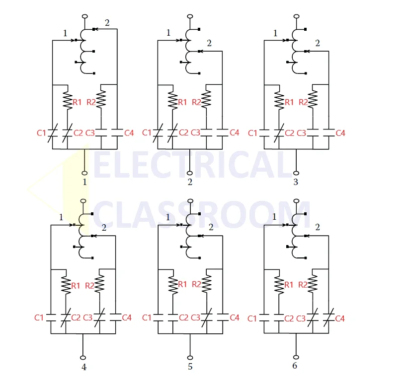
Here is a six step switching sequence of tap changer. This tap changer has two selector switches and an arcing switch with four contacts. (Follow the pictures below for each step.)
Step 1: This shows the steady state of the tap changer. Selector-1 is the conducting selector and contactors: C1 and C2 are closed. Selector-2 is the conducting selector and contactors: C3 and C3 are open. At this position the current flows to the load through C1.
Step 2: The selector-2 is moved to the desired tap position with contactors: C1 and C2 are closed and contactors: C3 and C3 are open. At this position the current flows to the load through C1.
Step 3: With the selector-2 at the desired tap position, contactor C1 is opened and C2 is still closed and contactors: C3 and C3 are still open. At this position the current flow the load happens through R1 and C2.
Step 4: With the selector-2 at the desired tap position, C3 is closed.
Step 5: With the selector-2 at the desired tap position, contactor C2 is opened and C3 is still closed and contactors: C1 and C4 are open. At this position the current flow the load happens through R2 and C3. Now the tap position 1 is opened and the load is transferred to tap 2.
Step 6: C4 is closed and the current to the load now flows through C4.
Since the full load current flows through the resistors from the step 3 to the step 5, the resistors must be selected in such a way that the they must be capable of withstanding the full load current plus the circulating current during the transition. The time of the entire transition must be shortened in order to lessen the energy absorption demand for the resistors. These tap changers typically feature very quick transitions.
Reactive switching
Reactors can be used to for switching the taps in the place of resistors. They does not dissipate energy as much as the resistors do. Hence they can be designed to withstand the full load plus the circulating current for long periods of time, even continuously. A six step switching with reactors can be more efficient than resistive switching.
External references:
Please don’t use the term no-load tapchanger. This type of tap-changer does not exist. 3 people died when attempting to adjust taps with the transformer energised on the primary side but off-load by virtue of the LV side circuit breaker being open.