A TRIAC or TRIode for Alternating Current is a three-terminal bidirectional thyristor, meaning that can conduct current in both directions when activated properly. It is used in AC switching applications. It can be considered as two SCRs connected in antiparallel. Unlike a silicon-controlled rectifier, it is capable of conducting positive and negative cycles of electric current.
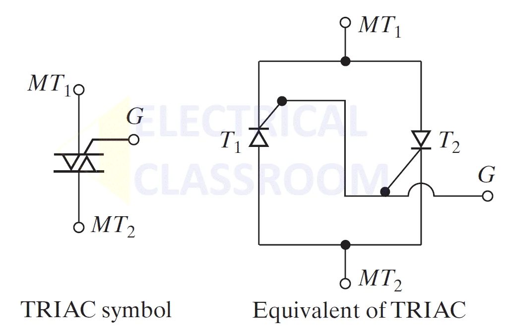
Symbol of TRIAC
The symbol of TRIAC and its equivalent circuit is shown in the above picture. It has two conducting main terminals MT1 (Main terminal-1) and MT2 (Main terminal-2), and a gate signal terminal G. The equivalent circuit shows the two-SCR model of a TRIAC.
Construction of TRIAC
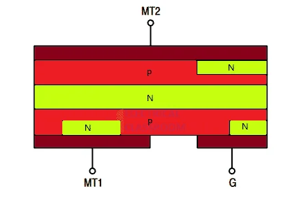
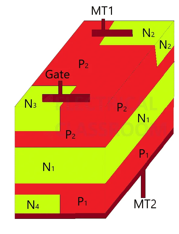
As mentioned earlier, a TRIAC looks like two SCR thyristors connected in anti-parallel and shares a common gate. Its basic structure is shown below:
It is a 5-layered device. As the equivalent circuit shows, these layer makes up two complementary SCRs with a common gate. The region between MT1 and MT2 behaves like a P-N-P-N SCR in parallel with N-P-N-P SCR. Since MT1 and MT2 have contact with both p and n regions, they cannot be designated as anode or cathode.
Working of TRIAC
The TRIAC can be turned on by applying a gate signal. The polarity of the gate signal depends on the polarity of MT1 and MT2. If MT2 is positive with respect to MT1, it can be turned on by applying a positive gate signal with reference to MT1, and if MT1 is positive with respect to MT2, it can be turned on by applying a negative gate signal with reference to MT1. When in operation it blocks both positive and negative voltages if there is no gate signal and the applied voltage is less than its breakdown voltage.
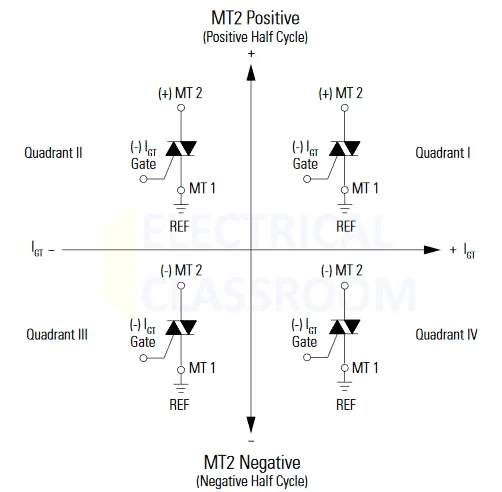
To fully understand the operation of a TRIAC, it is necessary to understand how it responds to positive and negative gate signals. Based on the polarity of the gate signal and that of the applied voltage four triggering quadrants can be defined.
Four quadrant operation of TRIAC
| Triggering quadrant | Polarity of gate | Polarity of MT2 |
|---|---|---|
| Quadrant I | Positive with respect to MT1 | Positive with respect to MT1 |
| Quadrant II | Negative with respect to MT1 | Positive with respect to MT1 |
| Quadrant III | Negative with respect to MT1 | Negative with respect to MT1 |
| Quadrant IV | Positive with respect to MT1 | Negative with respect to MT1 |
Quadrant I operation
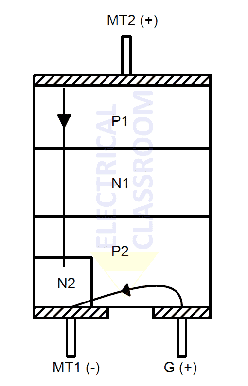
- MT2 and Gate positive with respect to MT1.
- Junctions P1N1 and P2N2 are forward biased.
- N1P2 is reverse biased. Therefore the TRIAC does not conduct until gate voltage is applied.
- On the application of positive gate voltage, P2N1 junction becomes forward biased and breaks down just like a normal SCR and the TRIAC starts conducting through P1N1P2N2 layers.
- Therefore during the first quadrant operation, the device operates like an SCR which makes it more sensitive in this mode.
Quadrant II operation
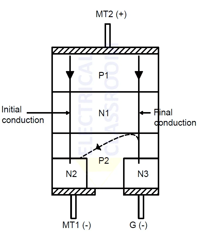
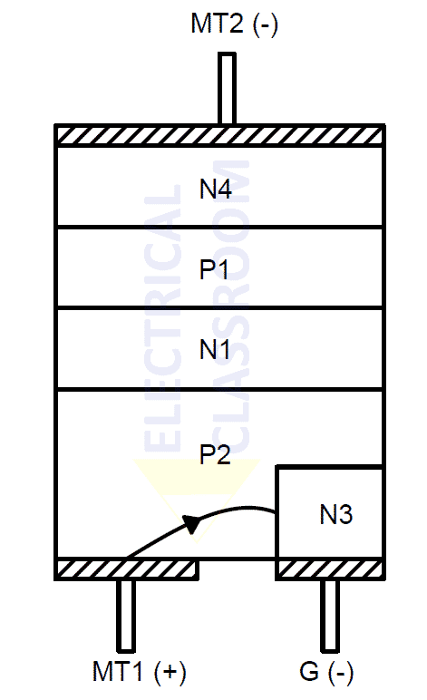
- MT2 is positive with respect to MT1 and gate is negative.
- Junctions N1P1 and N2P2 are forward biased.
- Junction N1P2 is reversed biased.
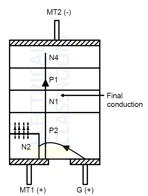
- When a negative gate current is applied to N3, N1P2 becomes forward biased and initial conduction happens through N1P1 P2 N3.
- In addition to that, a current flow is established towards the N2 region through P2 due to the potential gradient formed due to MT1.
- As a result, a current flow is established through N1P1N2P2.
- Thus it can be stated that the MT1 current acts as the gate current for the main conduction path (N1P1N2P2).
- When compared to Quadrant-I, Quadrant-II operation
Quadrant III operation
- MT2 is negative with respect to MT1 and gate is negative.
- The conventional gate current flows from MT1 to the gate terminal through P2N3.
- The reverse-biased junction N1P1 is broken and the current flows through P2N1P1N4.
- Like Quadrant-I, Quadrant-III operation is also more sensitive.
Quadrant IV operation
- MT2 is negative with respect to MT1 and gate is positive.
- The junction N2P2 is forward biased by the gate current which in turn injects more electrons into P2.
- As a result junction N1P1 is broken and the current flows through P2 N1 P1N4.
Characteristics of TRIAC
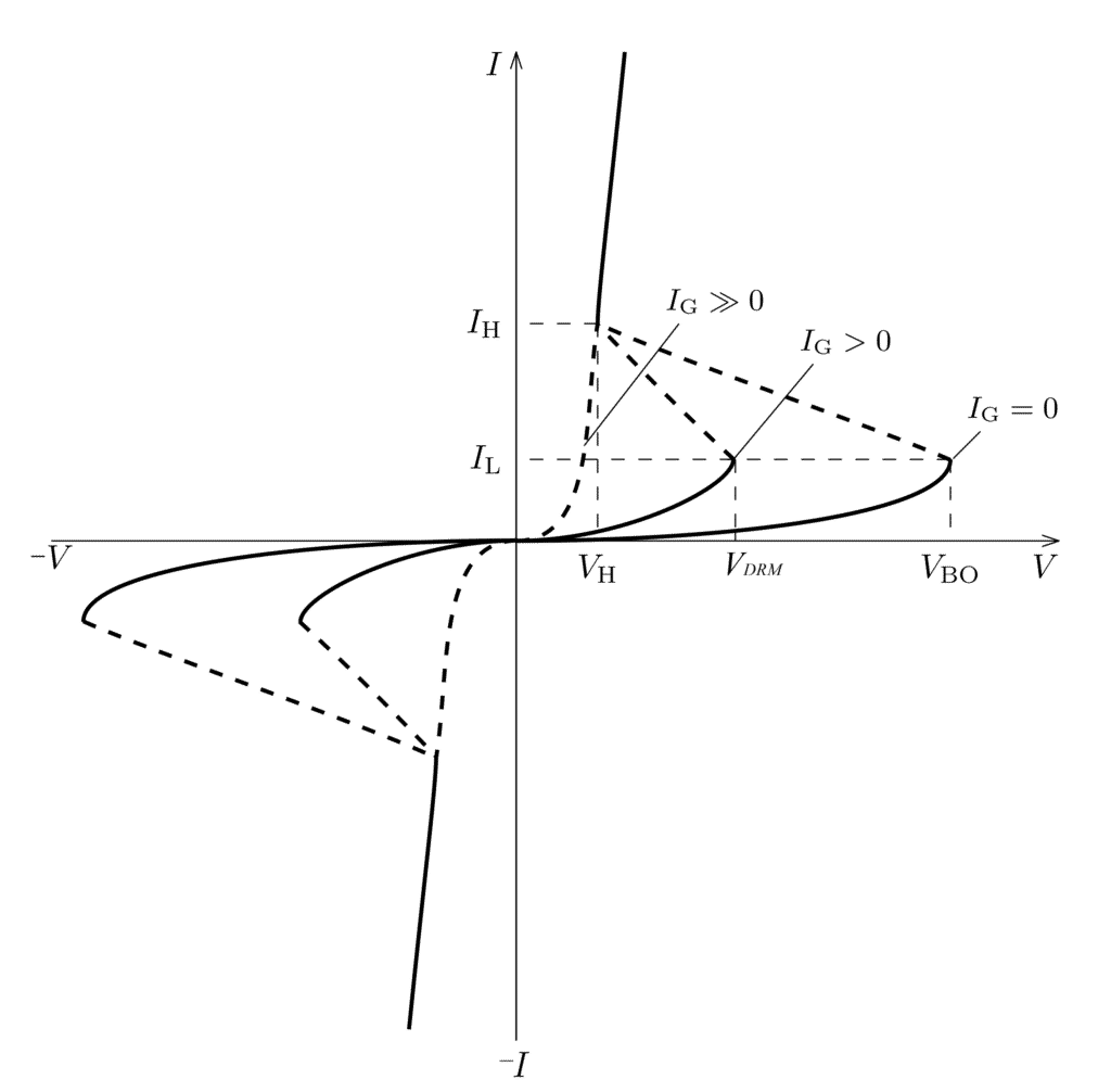
The following characteristic curve shows a few terms that define the operating characteristics of the TRIAC.
VBO is the break-over voltage. The break-over voltage is the maximum voltage the TRIAC can withstand before it enters uncontrolled conduction. This means that no more gate trigger voltage would be necessary for the device to remain in conduction mode.
Peak repetitive voltage (VDRM ) is the maximum peak voltage of the AC wave that can be tolerated by the device.
The minimum current required to cause the TRIAC to latch is known as the latching current (IL).
If the current falls below a particular threshold value the current will stop conducting. This minimum current holding value is knowns as the holding current (IH).
Advantages and Disadvantages of TRIAC
Advantages
- It is easy to use and is much cheaper than using two SCR thyristors separately for lower power applications.
- It can be triggered into a conduction state with both positive or negative polarity gate voltage and current pulses.
- It only requires a single large size heat sink unlike a single SCR thyristor which requires two heat sinks but of smaller size.
- Only a single fuse is required to provide the TRIAC with protection.
Since it is a bilateral device a safe breakdown voltage in either direction is possible, unlike the SCR which requires a diode connected in parallel to guarantee protection.
Disadvantages
- They are not as reliable as SCR.
- The change in voltage rating is much lower compared to the SCR.
- The triggering circuit needs to be carefully monitored at all times as it can be triggered into conduction in either direction.
Application
TRIACs are widely used for domestic light dimmers, small motor controls, electrical fan speed controls, and controlling small AC-powered domestic applications.
AC switching Applications
TRIACS main purpose is to be used in the switching of AC voltages. The figure below shows an example of an application that makes use of the TRIAC circuit for AC switching.
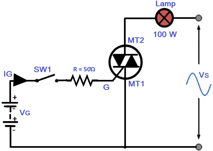
When the switch SW1 is open there will be no gate current supply which would result in no current flowing through the lamp. When the switch is closed then it would be turned ON. This would allow the current to flow through the resistor R and a pulse would be provided to the gate terminal which would initiate the conduction through the TRIAC circuit once the break over voltage is reached. Hence, AC voltage Vs will then be allowed to flow through the circuit which would light up the lamp.
TRIAC Phase Control
TRIACS are used to control the average power provided to a load. The TRIAC is triggered in such a way that the supplied AC power for a load is controlled through a portion of each half-cycle.
During the first half of the positive half cycle, it is switched off for a particular interval and then switched on during the remaining portion of the half-cycle. The portion of the positive cycle it is switched off is known as the delay angle and the portion it is switched on is known as the conduction angle. The action is similar for the other half of the AC waveform.
This type of phase control application makes use of two diodes to provide trigger pulses to the TRIAC gate. Diode (D1) conducts during the positive part of the half-cycle and the second diode (D2) conducts during the negative half cycle. The load resistance value of R1 sets the threshold value at which the TRIAC would trigger the conduction state.
Dimmer circuit using TRIAC
A simple TRIAC based dimmer circuit is shown in the figure. The brightness of the lamp can be controlled by varying the potentiometer.
Types of TRIAC
Pin or standard Type:
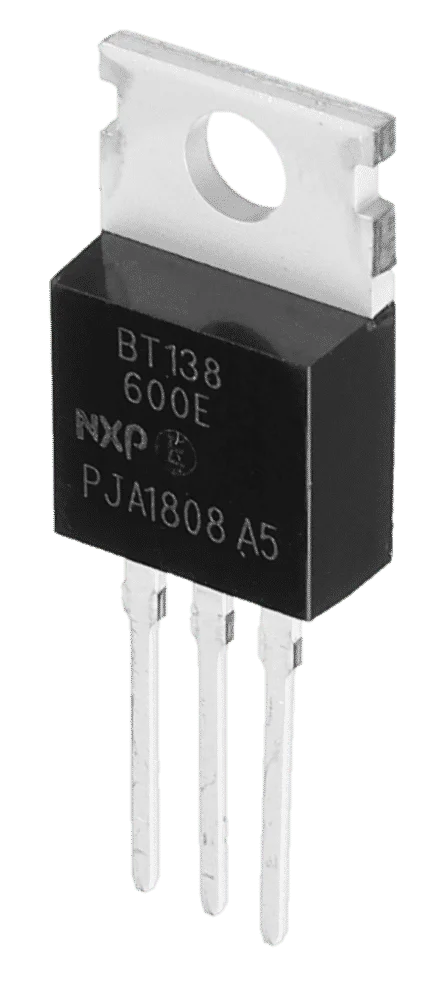
This type of TRIAC looks like a small IC which has three pins that are the MT1, MT2 and the gate with a heat sink on the top. They are commonly used in domestic appliances.
Capsule or disc Type:
This type of TRIAC is in the shape of a disc or capsule. It has wires which are extended to the terminals. They have a high current carrying capability and are made of the ceramic seal. They are widely used in applications such as AC switching and fast motor control.
Stud Type:
Stud type devices are used in high power applications. They comprise a screwed bottom that acts as the main terminal and has two terminals on the top. One terminal is the other main terminal and the second terminal on the top is the gate terminal. It is used in phase control applications such as converters, regulated power supplies, speed, wind or temperature-controlled circuits, power supply control, motor control, and lighting circuits.
Summary
- A TRIAC is a three-terminal, five-layered, bidirectional power electronic switching device.
- It acts like two anti-parallel SCRs connected for bidirectional operation.
- It has three terminals: MT1, MT2, and gate. MT1 and MT2 are interchangeable.
- The sensitivity of TRIACs is higher in the first quadrant and the second quadrant.
- TRIACs are commonly used in low-power AC control circuits.
- They are commonly used in dimmers, single-phase speed control, and heat control.
- Sample TRIAC datasheet: https://www.mouser.in/datasheet/2/848/bt139-600e-1520116.pdf


Hi,
Thanks for the putting this together. Just a typo in Q1 operation: “MT2 and Gate positive with respect to MT2.”
Thanks & Regards
Orhun Bicakci
Nice observation. Thank you for letting us know.