A Rogowski coil is an electrical transducer, that functions similar to a current transformer and is used in a variety of applications to measure alternating current (AC). It is named in honor of German physicist Walter Rogowski for his contributions to the field of electronics. Construction-wise they are a bit different from the normal current transformers. Also, they require additional signal processing circuits.
Working principle of Rogowski coils
The working principle of the Rogowski coil is based on Faraday’s law that states the total electromotive force induced in a closed circuit is proportional to the rate of change of the total magnetic flux linking the circuit.
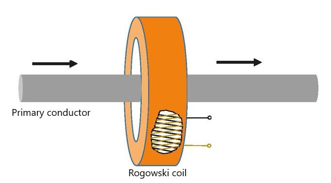
Unlike current transformers, Rogowski coils do not have separate primary and secondary coils. Instead, they consist of a wire wound on a non-magnetic core and the coil is then placed around conductors whose currents are to be measured. Therefore, the conductor carrying current acts like a primary winding, and the wire acts as a secondary coil.
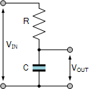
Since there is no magnetic core between the primary conductor and the Rogowski coil, the magnetic coupling between them will be so weak. The output of the coil shall be proportional to the current flowing through the conductor but will be significantly low to be used with measuring devices. Hence to achieve a quality signal, the output of the coil can either be integrated with a passive network as an R/C low-pass filter or with an operational amplifier. These output processing circuits are known as integrators.

(b) Structure Diagram of PCB Rogowski coil
The current flow through the conductor generates a magnetic field around it. The magnetic field intensity ‘B’ at a spatial point at a distance ‘r’ from the current-carrying conductor, when i(t) is the current flowing through the current-carrying conductor, μ0 is the vacuum permeability is given by the following equation:
The flux through the coil with the area of cross-section dA is given by
For the coil with N number of turns, height ‘h’, and width ‘dr’, the total flux through the coil is given by
According to Lenz’s law, the voltage induced in the coil is given by:
V(t) is the voltage induced in the coil and M is the mutual inductance between the conductor and the coil. The induced electromotive force of the Rogowski coil is proportional to the measured current. If the current flowing through the conductor is sinusoidal in nature, with a magnitude of Im, then the voltage induced is given by
The output voltage of the coil is proportional to the current flowing through the conductor with respect to time. Because of the cosine function, the signal output lags the current by 900.
At t=0, the peak induced voltage proportional to the current flowing through the conductor is given by:
The RMS value of the induced voltage is given by:
Rogowski coil types and design
A simple Rogowski coil consists of N turns of coil per meter wound on a non-magnetic former of constant cross-sectional area A. The winding wire is brought back to where it started, and the two ends are commonly attached to a cable. On the basis of design, Rogowski coils are classified into the following types:
- Rigid core coils
- Flexible core coils
- PCB coils
Rigid core coils
Rigid core Rogowski coils are made by winding coils on nonmagnetic cores. The cores are usually toroidal in shape and are made of plastic, epoxy, or other insulating material. The advantage of using nonmagnetic cores is obtaining the coil linearity since non-ferromagnetic material cannot saturate at high currents. The winding can be single or multi-layered. Single-layer windings have lower values of mutual inductance, series self-inductance, series resistance, and distributed capacitance than multi-layer coils that consist of two windings wound over each other.
Flexible core coils
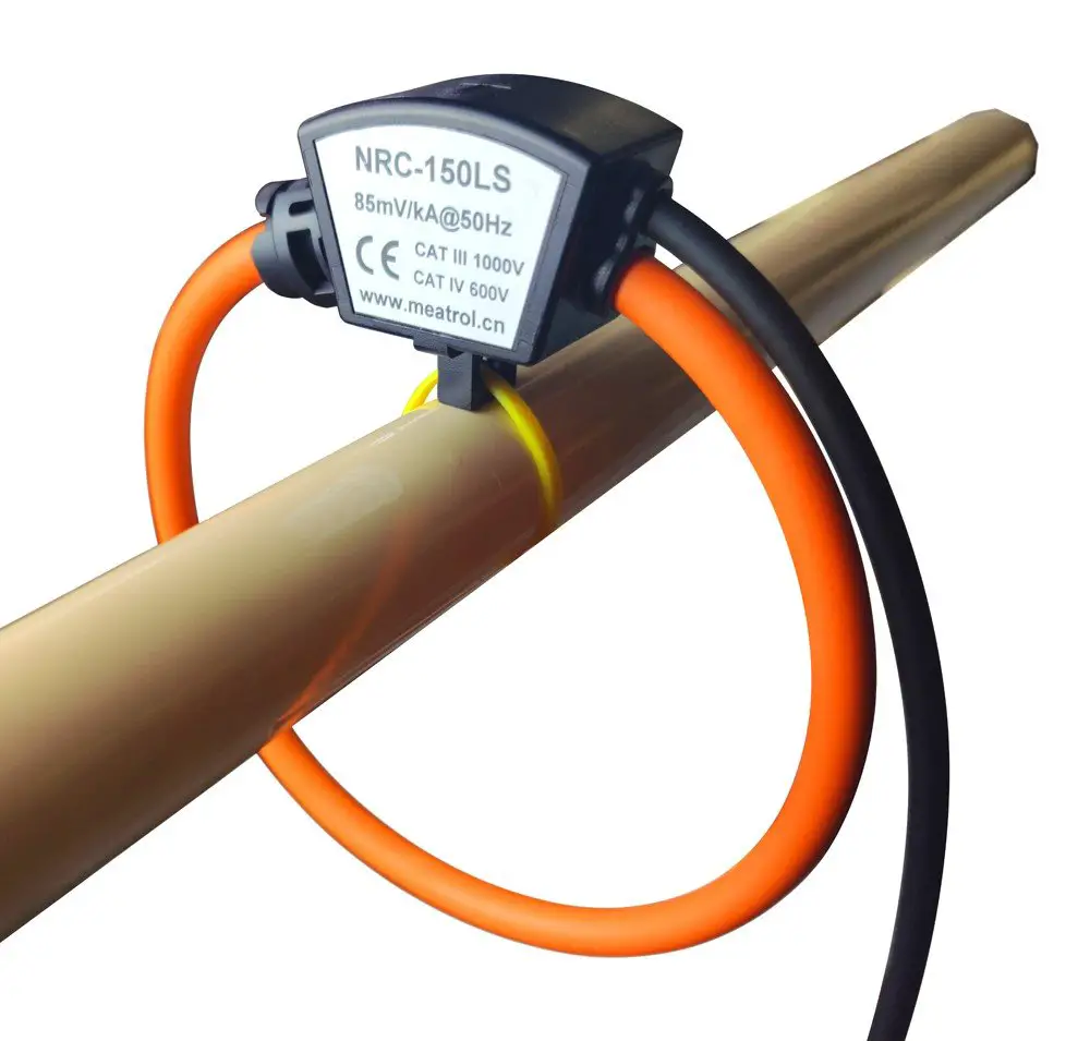
Flexible core Rogowski coils are very convenient to use as they can be used around all types of conductors and can be used in places with space constraints. They are made by winding a single layer of coil-over a silicone rubber core and returning it back to where it has started. The core can be split and attached around any electrical installations without interrupting the current flow through the conductors.
PCB Rogowski coils
PCB Rogowski coils are used to measure the amplitude of high-frequency current pulses PCBs. They are very commonly used to measure currents in IGBT modules. Since PCB Rogowski coils have a very small thickness, they can also be easily integrated into a press pack IGBT module.
Integrator
In order to use Rogowski coils with the measurement devices, the output of the coil should be passed through an integrator circuit. The Rogowski coil integrator can be a self or external integrator. Internal integrators have a narrow measurement bandwidth, a low sensing gain, and a weak output signal, making them best suited for monitoring high frequency and huge currents. The low-frequency currents can be measured externally with a fair amount of sensitivity.
The simplest form of integretor is a passive integretor, which is composed of an RC network. To prevent the low frequency component of the signal from being distorted and the integrator’s high frequency response capabilities from degrading, the passive integrator must employ an integrator with a large RC time constant. The RC network may as an attenuator and detoriate the output signal quality.
Active integrators are not easily affected by the load connected to the output. However, because the active integrator will increase its low-frequency gain, amplify, and affect the measurement results, the active integrator’s range should not be overly broad.
Hybrid integrators is the combination of both active and passive integrator circuits. To address the drawbacks of the conventional inverse integrator, the in-phase integrator circuit is used for the active integrator portion. The high frequency is integrated by the passive integrator, and the low frequency is integrated by the active integrator. The amplifier can keep its broad bandwidth in this fashion.
Applications of Rogowski coils
Rogowski coils is being used in various applications for decades due to its flexibility, accuracy and unlimited short circuit current tolerance. Here are a few key applications of Rogowski coils:
- Used for power and power quality monitoring. When combined with a variety of power quality analyzers, power recorders, and data loggers, they can confidently quantify transients and harmonics for the user.
- Rogowski coils in combination with protection relays, is used to sense/ detect faults in power systems and operate circuit breakers.
- Rogowski coils can be found within the circuit breakers for current sensing.
- They are used in frequency converters and inverters to sense the output currents of power electronic devices (IGBTs, MOSFETs etc).
- They are used to determine the losses in semiconductors.
- Rogowski coils are used in differential protection of power transformers.
- Used in differential protection of power lines and cables.
- Used in potable current measurement devices to measure current flows without interrupting the current flow through the conductors.
Advantages of Rogowski coils
- Rogowski coils are capable of measuring high currents without saturating the core making itself the most effective tool to measure large currents.
- Flexible core coils are lightweight and portable. They can be attached around any current carrying conductors.
- Rogowski coils are largely unaffected by stray fields that have a constant amplitude across the coil.
- No need to worry about leaving the secondary open.
Limitations of Rogowski coils
- Rogowski coils can be used with AC measurement only.
- Due to the lack of ferromagnetic cores and low coupling between the conductor and the coil, the induced voltage will be low. Hence, they need additional signal processing circuits.
References:
- Design of a PCB Rogowski Coil Based on the PEEC Method
- Wide Bandwidth Rogowski Current Transducers: Part II: The Integrator W.F. Ray


