Introduction
Classification of uncontrolled rectifiers
Uncontrolled rectifiers can be classified as follows:
- Half wave rectifier
- Full wave rectifier
- Bridge rectifier.
Of these three types of uncontrolled rectifiers, the most commonly used type is the bridge rectifier. Bridge rectifier is the most efficient of the three. So, let us discuss bridge rectifier first.
1. The Full Wave Bridge Rectifier
The Positive Half-cycle
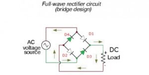
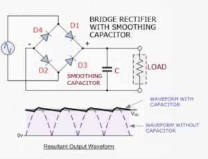
In a full wave bridge rectifier, two diodes will be conducting for each half cycle. The rest of the diodes will be reverse biased. During the positive half cycle of the supply, diodes D1 and D2 are forward biased and will be conducting. Diodes D3 and D4 are reverse biased and will not be conducting.
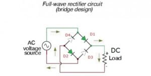
The Negative Half-cycle
During both the half cycles the current flowing through the load is unidirectional. Hence the voltage developed across the load is also unidirectional. The output voltage contains voltage ripples that can be controlled by connecting a capacitor in parallel to the load.
2. Half Wave Rectification
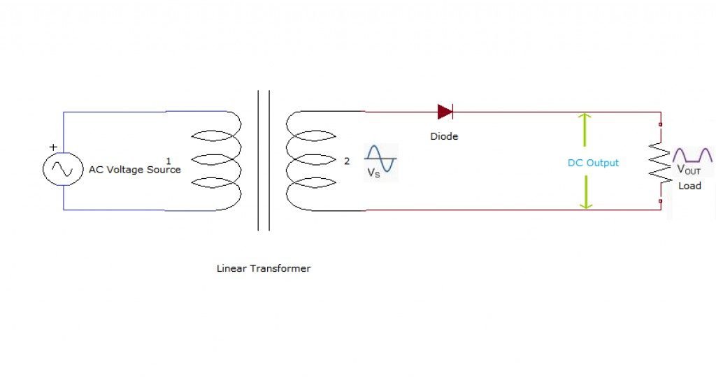
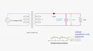
The half wave rectifier consists of a single diode connected in series with the load. In half wave rectification, when a single-phase AC supply is connected to a half-wave rectifier, the diode passes only the positive half cycle of the supply and blocks the negative half cycle. As the rectifier passes only a half of the supply it is called a half wave rectifier.
Half Wave Rectifier Circuit
During each positive half cycle of the AC sine wave, the anode is positive with respect to the cathode. Hence the diode is forward biased. Under the forward biased condition, the diode acts like a closed switch resulting in current flowing through the diode. During each “negative” half cycle of the AC sine wave, the anode is negative with respect to the cathode. Hence the diode is reverse biased and acts as an open switch. No current flows through the diode or circuit.
3. Full Wave Rectifier
The half wave rectifiers produce too much of ripples and the output current is not continuous. These drawbacks make it unsuited for many applications, especially in the circuits that require “steady and smooth” DC supply voltage. Ripples and efficiency can be improved using full wave rectifiers.
In full wave rectifiers we can obtain output voltage during the positive and negative half cycles. Therefore it delivers improved efficiency than the half wave rectifiers. It produces an output voltage that is purely DC. For the full wave rectifiers the average direct current output voltage is higher than that of half wave, the output of the full wave rectifier has much less ripple than that of the half wave rectifier producing a smoother output waveform.
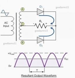
In a single phase, Full Wave uncontrolled Rectifier circuit two diodes are now used. Only one diode will be forward biased and conducts during each half cycle. A centre tapped transformer is used in full wave rectifier as shown in the figure.
Reduction of ripples in bridge rectifiers using smoothing capacitor
As mentioned earlier, the voltage ripples can be controlled by connecting a smoothing capacitor in parallel to the load. It converts the full wave rippled output of the rectifier into a smooth DC output voltage. But the usage of the capacitor is the circuit is limited by the cost factors and the size of the circuit. The smoothing capacitor controls the ripple as follows:
Commonly used smoothing capacitors are of 100uF or higher of aluminium electrolytic type. The parameters considered during the selection of appropriate capacitance value are its working voltage and capacitance value, which determines the number of ripples that appear at the output.
Reduction of ripples in half wave rectifier using Smoothing Capacitor
The direct voltage obtained after rectifications contains a certain amount of voltage ripples that can be reduced by using a large value of capacitance. For half-wave rectifiers, it is not necessary. This is because in half-wave rectifier will increase the ripple rather than reducing it. Half-wave rectifiers are not practically used in a circuit due to its reduced efficiency and more losses.
Applications of rectifiers.
Rectifiers are widely used in all electronic equipment to provide dc supply from the available AC supply. Controlled rectifiers are used in the high voltage Direct current transmission system to convert the generated AC power into DC power for transmission. Also, it is used in battery charges, home inverters etc.
Read more on diodes
- Types of Diodes(Click)
A Diode is a two-terminal electronic component which offer zero resistance in forward bias and infinite resistance in reverse bias. This article tells about various types of diodes.
Loving the way articles have been written