What are zener diodes?
Zener diodes are silicon semiconductor devices that can allow the passage of current in both forward and reverse directions. Unlike p-n junction diodes, they are designed in such a way to handle the reverse breakdown voltage without damaging themselves.
They are heavily doped than normal p-n junction diodes, thereby forming a very thin depletion region. This makes them capable of reverse breakdown at relatively low voltages (Typically less than 4V). Also, after reverse breakdown, the voltage across them stays fairly constant. This makes it suitable for use as voltage regulators.

During the reverse bias it conducts only a small leakage current. If the voltage in reverse mode increases to specified breakdown voltage (Vz) then, the flow of current from diode begins. A series resistor indicates that the current reaches the maximum first and after that it gets stabilized and then, for the wide range of applied voltage, it remains constant.
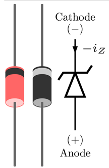
Symbol of Zener Diode
The picture shows the standard symbol of Zener diodes with the anode and cathode marked on respective sides. In an actual device, the cathode is indicated with a thick line. -iz indicate the reverse current flow after Zener breakdown.
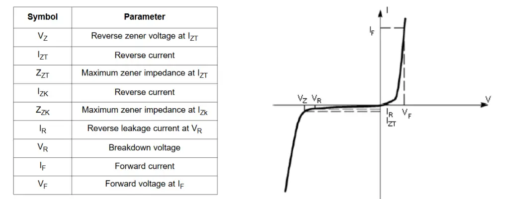
V-I Characteristics of Zener Diode
When the anode is connected with the positive terminal of the supply it is considered to be in forward bias and when the anode is connected to the negative terminal of the supply reverse biased mode.

Forward Characteristics of Zener Diodes
When forwards biased it works similar to the p-n junction diode. It has a bias voltage between 0.3V0.7V. It has the forward bias characteristics which are represented in the first quatrain of the V-I characteristics.
Reverse Characteristics of Zener Diodes
Even at reverse bias condition, a small amount of leakage current flows through the Zener diode. As the reverse voltage increases and reaches a particular level, it starts conducting as in the reverse bias mode without getting damaged. At this point the current increases steeply to the maximum value, as determined by the circuit component. The voltage at which the Zener diode translates from reverse blocking state to reverse conducting state is known as Zener voltage.
At the reverse conducting state it conducts for a wide range of voltages. Irrespective of the current flow, the voltage drop across the conductor remains constant.
Avalanche Breakdown in Zener Diodes
This type of breakdown occurs not only in Zener diode but also in normal diode at high reverse voltage. If the P-N junction is applied with high reverse voltage then the electrons move with high velocities because, they attain the sufficient amount of energy.
When these free electrons are accelerated with high velocities then, the collision of atoms occurs and more electrons are knocked off. As the collision occurs continuously, electrons keep on knocking off and this results in the increase of electric current in the diode at a continuous rate. Due to the abrupt increase of electric current, the normal diode can be destroyed permanently but, it has the ability to sustain this abrupt increase of current.
Zener Breakdown in Zener Diode
When the reverse-biased voltage and the other Zener voltage reach closer, the electric field in the depletion region increases and it pulls more electrons from the valence band. These electrons in valence band get separated from the parent atom due to high density of electric field in the depletion region. In this point, little amount of voltage increases that is enough to rapidly increase the electric current to the Zener breakdown region and there the breakdown occurs.
Specifications of Zener diode
Breakdown Voltage: There the breakdown voltage ranges from 2.4Volts to 200Volts.
Current (max) Iz: It represents the maximum current at the rated Zener Voltage and the value for Vz is from 200 micro-Ampere to 200 Ampere.
Current Iz (min): Lowest value of current which is required for the breakdown of diode.
Power Rating: It represents the maximum power consumed by the diode. It is the voltage and amount of current passing through the diode.
Temperature Stability: For the best temperature stability of diodes 5V is required.
Applications of Zener Diode
The major applications of Zener diodes are the following:
- Voltage regulation
- Over-voltage protection
- Clipper circuits
- Voltage shifting
Zener diode as voltage regulator:
The purpose of a voltage regulator is to maintain a constant load voltage irrespective of varying load current and supply voltages. In the case of Zener diodes, the Zener voltage gives it the capability of voltage regulation. At reverse conducting mode, the Zener diode keeps the voltage across its terminal constant always while adjusting the current flow through it. Hence the voltage across the load connected in parallel to it remains constant.

Over-voltage protection feature:
Zener diode in combination with SCR can mitigate risk of damage due to over voltages. As the voltage increases over the Zener voltage, the diode starts conducting and triggers the SCR, and provides a low resistance path for over-voltages to the ground, thus protecting the load from severe damages.

Clipper circuit
Two Zener diodes connected back to back can work as a waveform clipper. This can help in mitigating the spike voltages from affecting the load.
Summary
Zener diode is designed to operate safely in reverse bias mode and conduct a substantial amount of reverse current at bias voltages above Zener voltage. Zener voltage is the minimum voltage at which the diode starts conduction when reverse biased. Out of numerous applications, voltage regulation is the most important application of Zener diodes.
