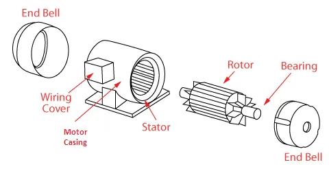
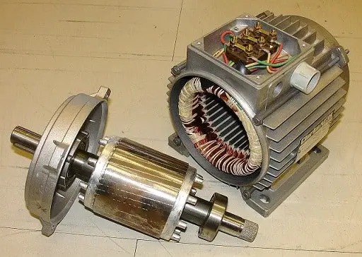
An electric motor converts electrical energy to mechanical energy. In general, an electric motor consists of a stator, a rotor, winding, bearings, and casing. The motor rotates due to the force of attraction or repulsion between the stator or rotor fields. This article provides you an overview of the parts of a motor.
Parts of a motor

Stator
The stationary parts of a motor are collectively known as a stator. The stator may contain windings or a permanent magnet. In the case of AC motors, the stator carries the armature and in DC motors it carries the field winding. The stator cores of AC motors are made of laminated silica steel while the DC cores need not be laminated.
Rotor
The rotor is the set of winding and magnetic core attached to which the motor shaft is attached. The rotor core is made of laminated silica steel. The rotor is replaced using a cage-like structure in the case of squirrel cage induction motors. The rotor delivers mechanical energy to the shaft. In PMAC motors, rotor windings are replaced by permanent magnets.
Commutator
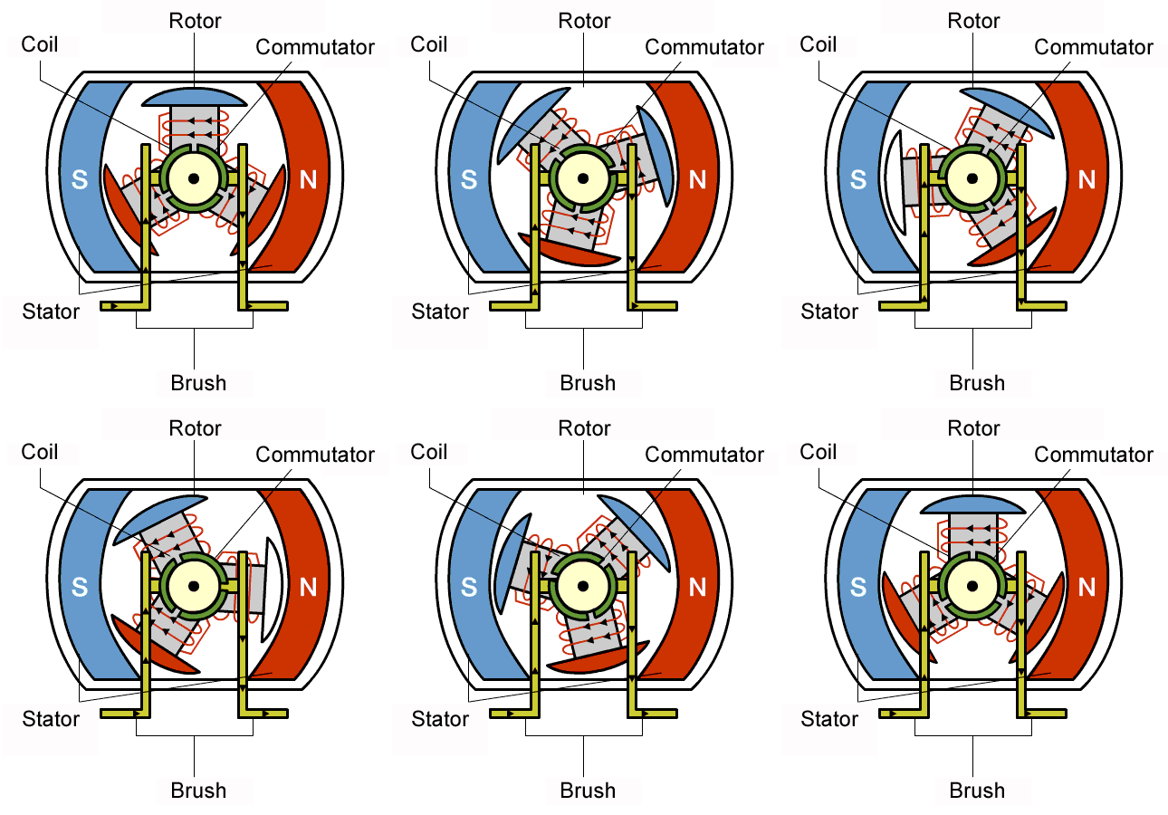
Commutators are used to reverse the direction of current in the rotor in order to maintain a repulsive force between the rotor and stator poles. They are found in all motor types which requires DC supply for their rotors. Voltage is applied to the rotor using spring-loaded carbon brushes that sit over the commutator.

Bearing and shaft assembly
The bearings support the rotor. It maintains the air gap and transfers the shaft load to the motor casing. The rotor core-winding assembly is mounted over the shaft. The shaft extends outside the casing and transfers the mechanical energy from the rotor to the load.
Insulation materials
Insulation protects the motor windings from short circuits and contamination. Paper, resins, rubber, varnish, enamel, mica, glass fiber, etc. are used as insulators.
Casing, brushes, and terminals
The motor casing supports the stator and other motor components as well as protect the stator and rotor components from the external environment. Normally they are made up of aluminum.
Carbon brushes are used to supply electricity to the rotor. It maintains contact with the commutator regardless of the speed of rotation. Contact pressure is maintained with the help of spring.
The operational power is supplied to motors through their terminals.
An electric motor works through the principle of electromagnetism. The rotor and stator windings that carry current act as an electromagnet, producing a force of attraction or repulsion between them. Typically DC motors working on the principle of electromagnetic repulsion whereas AC motors work through that of electromagnetic attraction. The typical parts of a motor are discussed above.
Other useful links
- Synchronous speed calculator
- Torque-power calculator
- Power-torque calculator
- Torque-speed calculator
- Speed-torque calculator
- Induction motor slip
- Motor torque calculator
- Motor FLC calculator
- Motor Locked rotor current calculator
- Number of poles calculator
- DOL Starter Design tool
- Star-Delta Starter design tool
- HP to kW Converter
- kW to Amps Converter
- Amps to kW converter


A very simple but extensive explanation.
Thank you for this very useful information.
I came to your webpage, trying to learn, how to remove the pulley wheel of my 1.75 hp GMC -240 Volt Motor, by allowing me taking out the Rotor from the other end.
I was thinking of using some kind of “Gear puller” tool, but what would I be looking for?
PS: have tried a Motor repair place, but their cost would be as much as the cost of a new motor (they told me) so I was hoping I could do it myself by finding out “how” professionals are doing it.
Thanks if you have any suggestions